 System Board Jumpers
Dell™ PowerEdge™ 840 Systems Hardware Owner's Manual
Disabling a Forgotten Password
This section provides specific information about the system jumpers and describes the connectors on the various boards in the system.

|
CAUTION: Only trained service technicians are authorized to remove the system cover and access any of the components inside the system. See your Product Information Guide for complete information about safety precautions, working inside the computer, and protecting against electrostatic discharge. |
Figure 6-1 shows the location of the configuration jumpers on the system board. Table 6-1 lists the jumper settings.

|
NOTE: To access the jumpers, remove the memory cooling shroud by lifting the release latch and sliding the shroud toward the front of the system. See Figure 3-14. |
Figure 6-1. System Board Jumpers
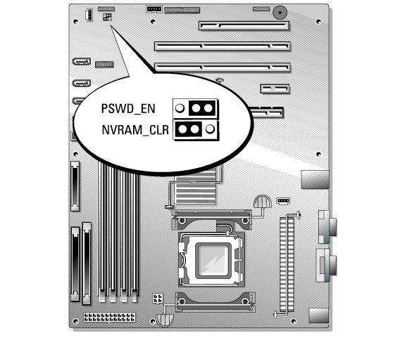
Table 6-1. System Board Jumper Settings
See Figure 6-2 and Table 6-2 for the location and description of the system board connectors.
Figure 6-2. System Board Connectors
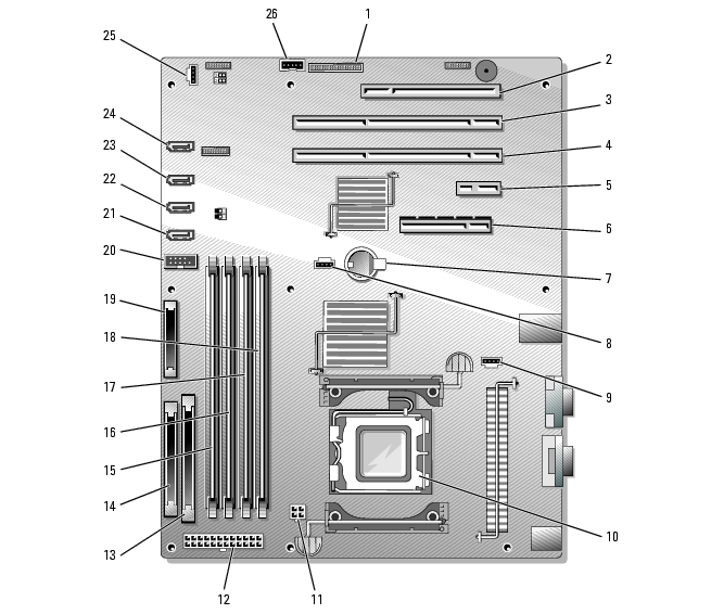
Table 6-2. System Board Connectors
|
Item |
Connector |
Description |
|---|---|---|
1 | RAC_CONN | Connector for the remote access controller (RAC) |
2 | SLOT_5 | PCI 32-bit, 33-MHz (5-V) expansion slot connector |
3 | SLOT_4 | PCI-X 64-bit, 133-MHz (3.3-V) expansion slot connector |
4 | SLOT_3 | PCI-X 64-bit, 133-MHz (3.3-V) expansion slot connector |
5 | SLOT_2 | PCI-Express (x1) expansion slot connector |
6 | SLOT_1 | PCI-Express (x8) expansion slot connector |
7 | BATTERY | Connector for the 3.0-V coin battery |
8 | HD | Hard drive LED activity connector |
9 | BACK_FAN | Fan power connector |
10 | CPU | Processor connector |
11 | 12V | Power connector |
12 | PWR_CONN | Power connector |
13 | IDE | IDE optical device connector |
14 | FDD | Diskette drive connector |
15 | DIMM2_ B | Memory module connector |
16 | DIMM1_ B | Memory module connector |
17 | DIMM2_ A | Memory module connector |
18 | DIMM2_ A | Memory module connector |
19 | FRONT_PANEL | Control panel connector |
20 | USB | USB 2.0-compliant connector |
21 | SATA_0 | SATA connector |
22 | SATA_1 | SATA connector |
23 | SATA_2 | SATA connector |
24 | SATA_3 | SATA connector |
25 | FRONT_FAN | Fan power connector |
26 | BP_I2C | Connector for the baseboard management controller (BMC) inter-IC (I2C) cable for the optional SCSI backplane |
The system's software security features include a system password and a setup password, which are discussed in detail in Using the System Setup Program. The password jumper enables these password features or disables them and clears any password(s) currently in use.
|
|
CAUTION: Only trained service technicians are authorized to remove the system cover and access any of the components inside the system. Before performing any procedure, see your Product Information Guide for complete information about safety precautions, working inside the computer, and protecting against electrostatic discharge. |
See Figure 6-1 to locate the password jumper on the system board.
The existing passwords are not disabled (erased) until the system boots with the password jumper plug removed. However, before you assign a new system and/or setup password, you must install the jumper plug.
|
|
NOTE: If you assign a new system and/or setup password with the jumper plug still removed, the system disables the new password(s) the next time it boots. |
To assign a new password using the System Setup program, see Using the System Setup Program.