Back to Contents Page
Installing System Components
Dell™ PowerEdge™ 840 Systems Hardware Owner's Manual
 Recommended Tools
Inside the System
Opening the System
Front-Panel Drive Inserts
Closing the System
Connecting Drives
Diskette Drive
Optical or Tape Drives
Hard Drives
Cooling Shroud
Cooling Fans
Power Supply
Expansion Cards
Memory
Microprocessor
Installing a RAC Card
System Battery
Front I/O Panel (Service-Only Parts Procedure)
System Board (Service-Only Parts Procedure)
This section describes how to install the following system components:
- Diskette drive
- Optical and tape drives
- Hard drives
- Cooling Shroud
- Cooling Fans
- Power supply
- Expansion cards
- Memory
- SAS controller card
- Microprocessor
- System battery
- Front I/O panel
- System board
Recommended Tools
You may need the following items to perform the procedures in this section:
- #2 Phillips screwdriver
- Long #2 Phillips screwdriver (blade at least 6 inches long)
- Small flat-blade driver
- Wrist grounding strap
Inside the System
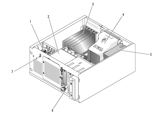
In Figure 3-1, the system cover is opened and the front bezel removed to provide an interior view of the system.
Figure 3-1. Inside the System
|
1
|
front fan
|
2
|
drive cage
|
3
|
expansion cards (optional)
|
|
4
|
cooling shroud
|
5
|
power supply
|
6
|
5.25-inch drive bays (2)
|
|
7
|
chassis-intrusion switch
|
|
|
|
|
The system board can accommodate a single processor, five expansion cards, and four memory modules. The hard-drive cage provides space for up to four SAS or SATA hard drives. Two 5.25-inch external drive bays in the front of the system can accommodate optical or tape drives; a single 3.25 drive can accommodate an optional diskette drive. A controller expansion card is required to use SAS hard drives. Power is supplied to the system board and internal peripherals through a single, nonredundant power supply.
Opening the System

|
CAUTION: Only trained service technicians are authorized to remove the system cover and access any of the components inside the system. Before performing any procedure, see your Product Information Guide for complete information about safety precautions, working inside the computer and protecting against electrostatic discharge. |
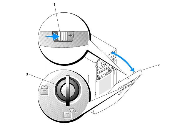
Removing the Bezel
You must remove the bezel to remove the system cover.
- Using the system key, unlock the bezel. See Figure 3-2.
- Slide the bezel latch toward the right side of the system.
- Swing the top of the bezel away from the system, disengage the hooks at the bottom of the bezel, and
lift the bezel away from the system.
Figure 3-2. Removing the Bezel
|
1
|
bezel latch
|
2
|
bezel
|
3
|
keylock
|
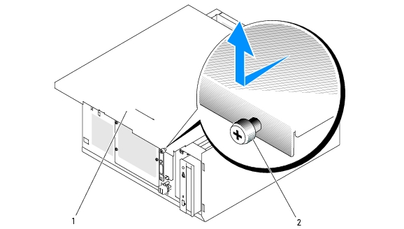
Removing the Cover
|
|
CAUTION: Only trained service technicians are authorized to remove the system cover and access any of the components inside the system. Before performing any procedure, see your Product Information Guide for complete information about safety precautions, working inside the computer and protecting against electrostatic discharge. |
- Turn off the system and attached peripherals, and disconnect the system from the electrical outlet.
- Remove the bezel. See Removing the Bezel.
- Lay the system on its right side.
- Loosen the thumbscrew at the front of the system. See Figure 3-3.
- Slide the cover forward and grasp it at both ends.
- Lift the front edge of the cover 2.5 cm (1 inch), slide the cover toward the top of the system, and then
lift the cover away from the system.
Figure 3-3. Removing the Cover
|
1
|
system cover
|
2
|
thumbscrew
|
|
|
Front-Panel Drive Inserts
To help keep dust and dirt out of the system, a plastic insert covers each empty external drive bay. Additionally, each empty external drive bay is covered by a metal insert in the chassis to maintain Federal Communications Commission (FCC) certification of the system.
Before you install a 5.25-inch drive in an empty external drive bay, you must first remove both front-panel drive inserts. If you remove a 5.25-inch drive permanently, you must install both inserts.
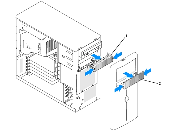
Removing the Front-Panel Drive Inserts
|
|
CAUTION: Only trained service technicians are authorized to remove the system cover and access any of the components inside the system. Before performing any procedure, see your Product Information Guide for complete information about safety precautions, working inside the computer, and protecting against electrostatic discharge. |
- Turn off the system, including any attached peripherals, and disconnect the system from the electrical
outlet.
- Remove the bezel. See Removing the Bezel.
- Remove the bezel drive insert (see Figure 3-4):
- From inside the bezel, press the center of the insert outward with your thumbs to loosen the tabs
on the sides of the insert.
- Pull the insert out of the bezel.
- Remove the chassis drive insert (see Figure 3-4):
- Press both sides of the insert to loosen the tabs on the insert.
- Pull the insert out of the chassis.
Figure 3-4. Removing the Front-Panel Drive Inserts
|
1
|
chassis drive insert
|
2
|
bezel drive insert
|
|
|
Installing the Front-Panel Drive Inserts
|
|
CAUTION: Only trained service technicians are authorized to remove the system cover and access any of the components inside the system. Before performing any procedure, see your Product Information Guide for complete information about safety precautions, working inside the computer, and protecting against electrostatic discharge. |

|
NOTICE: You must install both inserts in an empty 5.25-inch drive bay to maintain Federal Communications Commission (FCC) certification of the system. The inserts also help keep dust and dirt out of the system. |
- Install the chassis drive insert by sliding the insert into the chassis until tabs on the side of the insert
snap into place. See Figure 3-4.
- Install the bezel drive insert by sliding the insert into the bezel until the tabs on the side of the insert
snap into place. See Figure 3-4.
- Install the bezel. See Installing the Bezel.
- Reconnect the system to its electrical outlet and turn the system on, including any attached
peripherals.
Closing the System
Replacing the Cover
- Ensure that all cables are connected, and fold cables out of the way.
- Ensure that no tools or loose parts are left inside the system.
- Fit the cover on the side of the system, and slide the cover backward.
- Tighten the cover thumbscrew to secure the cover.
Installing the Bezel
To install the bezel, align the hooks at the bottom of the bezel, swing the top of the bezel toward the system, and press the bezel onto the system until it snaps into place. Using the system key, lock the bezel.
Connecting Drives
Interface Cables
Most interface connectors are keyed for correct insertion. Keying ensures that the pin-1 wire in the cable connects to pin 1 in the connectors on both ends. When you disconnect an interface cable, take care to grasp the cable connector, rather than the cable itself, to avoid stress on the cable.
Drive Cable Configurations
Your system can accommodate many different drive configurations, each with specific cable requirements. Table 3-1 shows the cable requirements for common drive configurations.
Table 3-1. Drive Cable Configuration
|
Drives
|
Required Cable
|
Cable Connections
|
|---|
IDE optical drives, internal IDE and external SCSI tape drives (with optional SCSI HBA card) (See Figure 3-7.)
| 80-pin IDE 2-drop cable or external SCSI cable
| IDE drive and primary IDE connector on system board or external SCSI tape device (with option SCSI HBA card)
|
Up to four cabled SATA hard drives (non-hot-plug) (See Figure 3-9.)
| 7-pin SATA hard-drive cable (one cable per drive)
| SATA hard drives and SATA port connectors on the system board, or via SAS controller card
|
Up to four cabled (non-hot-plug) SAS hard-drives (See Figure 3-13.)
| 32-pin 1- to 4-drop SAS cable
| SAS hard drives connected to SAS controller card
|
Up to four SAS or SATA hard drives connected to the SAS backplane (hot plug) (See Figure 3-12.)
| 32-pin SAS backplane cable
| SAS backplane connected to the SAS controller card
|
DC Power Cables
Each drive must connect to a DC power cable from the system power supply. These power cables are used for the 3.5-inch diskette drive, 5.25-inch devices, and hard drives.
|
|
NOTICE: To avoid electrical damage to internal system components, install a cover connector on any unused connectors on hard-drive power cables. |
Diskette Drive
Removing a Diskette Drive
|
|
CAUTION: Only trained service technicians are authorized to remove the system cover and access any of the components inside the system. Before performing any procedure, see your Product Information Guide for complete information about safety precautions, working inside the computer, and protecting against electrostatic discharge. |
- Turn off the system, including any attached peripherals, and disconnect the system from the electrical
outlet.
- Open the system. See Opening the System.
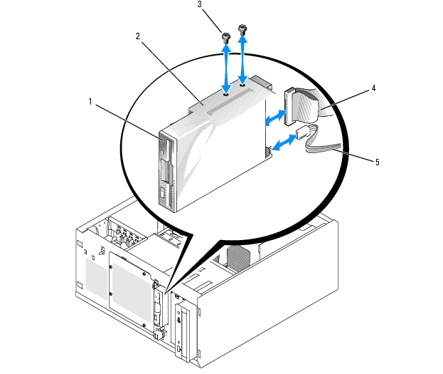
- Disconnect the power cable and the interface cable from the diskette drive. See Figure 3-5.
- Remove the two screws that secure the diskette drive in the externally accessible drive bay. See
Figure 3-5.
- Slide the diskette drive forward out of the drive bay.
Installing a Diskette Drive
|
|
CAUTION: Only trained service technicians are authorized to remove the system cover and access any of the components inside the system. Before performing any procedure, see your Product Information Guide for complete information about safety precautions, working inside the computer, and protecting against electrostatic discharge. |
- Unpack the drive and prepare the drive for installation.
For instructions, see the documentation that accompanied the drive.
- Slide the diskette drive into the externally accessible drive bay.
- Install the two screws that secure the diskette drive in the drive bay. See Figure 3-5.
- Connect the power cable and the interface cable to the diskette drive. See Figure 3-5.
- Close the system. See Closing the System."
- Stand the system upright.
- Reconnect the system to its electrical outlet and turn the system on, including any attached
peripherals.
Figure 3-5. Removing or Installing a Diskette Drive
|
1
|
diskette (3.5-inch) drive
|
2
|
externally accessible drive bay
|
3
|
screws (2)
|
|
4
|
interface cable
|
5
|
power cable
|
|
|
Optical or Tape Drives
An optical drive is standard in the first external drive bay. An additional IDE or SCSI tape drive can be installed in the second external drive bay. These drives connect either to the system board or to an optional controller card.

|
NOTE: Installing an additional optical drive in the second external drive bay is not supported. |
Installing an Optical or Tape Drive
|
|
CAUTION: Only trained service technicians are authorized to remove the system cover and access any of the components inside the system. Before performing any procedure, see your Product Information Guide for complete information about safety precautions, working inside the computer, and protecting against electrostatic discharge. |
- Unpack the drive (and controller card, if applicable), and prepare the drive for installation.
For instructions, see the documentation that accompanied the drive.
|
|
NOTE: If you are installing a SCSI tape drive, you must install an Ultra 3 SCSI controller card. The optional SAS controller card does not support a SCSI tape drive. |
- Turn off the system, including any attached peripherals, and disconnect the system from the electrical
outlet.
- Open the system. See Opening the System.
- Remove the front-panel inserts for the empty external drive bay. See "Removing the Front-Panel Drive
Inserts.
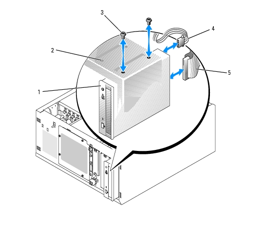
- Slide the drive into the external drive bay.
- Install the screws that secure the drive in the drive bay. See Figure 3-6.
Figure 3-6. Installing or Removing an Optical or Tape Drive
|
1
|
5.25-inch drive
|
2
|
drive bay
|
3
|
screws (2)
|
|
4
|
power cable
|
5
|
interface cable
|
|
|
- If a controller card was supplied with the drive, install the controller card in expansion slot 3, 4, or 5.
See Installing an Expansion Card.
- Connect a power cable to the drive. See Figure 3-6.
- Connect the interface cable to the drive and to the appropriate connector on the system board or
controller card (if applicable).
|
|
NOTE: See the documentation that is included with the controller card for more information. |
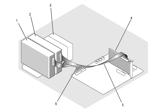
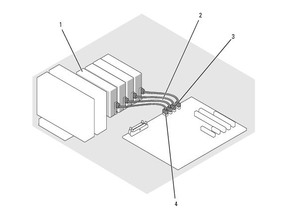
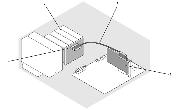
If you are installing an IDE device (such as an optical drive), connect the interface cable to the IDE device and the IDE connector on the system board. See Figure 3-7.
If you are installing a SCSI device in the second drive bay (such as a tape backup device), connect the interface cable to the device and to channel A on the SCSI controller card. See Figure 3-7.
See System Board Connectors to locate the system board connectors.
|
|
NOTE: A SCSI device attached to an optional SCSI controller card and an IDE device attached to the system board can be installed together as shown in Figure 3-7. |
Figure 3-7. Connecting a Tape Drive to a SCSI Controller Card
|
1
|
IDE device
|
2
|
optional SCSI device
|
3
|
hard drives (up to 4)
|
|
4
|
SCSI controller card
|
5
|
SCSI cable
|
6
|
IDE interface cable
|
- Ensure that all cables are firmly connected and arranged so that they will not catch on the computer
cover or block airflow inside the system.
- Close the system. See Closing the System.
- Stand the system upright.
- Reconnect the system to its electrical outlet and turn the system on, including any attached
peripherals.
- Test the drive.
If you installed an IDE device, run the IDE devices tests in the system diagnostics to determine whether the device operates properly. See Running the System Diagnostics.
If you installed a SCSI device, run the SCSI controllers test in the system diagnostics. See Running the System Diagnostics.
If you installed a tape drive, see the tape drive software documentation to perform a backup and verification test.
Hard Drives
|
|
NOTE: The system's drive configuration must consist of only SATA hard drives or only SAS hard drives. Combining SATA and SAS drives is not supported. |
Your system can contain up to four 1-inch-height SATA or SAS hard drives in either a removable fixed hard-drive bay (see Figure 3-8) or a lever-release bay (see Figure 3-11). These drives connect either to the system board, an optional controller card, or an optional SAS backplane.
SAS or SATA drives can be hot-pluggable only if they are attached to an optional SAS backplane. See Hot-Plug SATA Hard Drives Using the SAS Backplane, Hot-Plug SATA Hard Drives Using the SAS Backplane, and Removing and Installing the Optional SAS Backplane Board.
Hard Drive Installation Guidelines
Use the following guidelines when installing hard drives:
- You should only use drives that have been tested and approved by the system manufacturer.
- Do not install a mixture of SATA and SAS hard drives. All hard drives must either be SAS drives or SATA drives.
- You may need to use different programs than those provided with the operating system to partition and format a hard drive. See the hard drive documentation for information on setting up the drive.
- When you format a high-capacity hard drive, allow enough time for the formatting to be completed. Long format times for these drives are normal. For example, a large drive can take over an hour to format.
- Do not turn off or reboot your system while the drive is being formatted. Doing so can cause a drive failure.
Configuring the Boot Drive
The drive or device from which the system boots is determined by the boot order specified in the System Setup program (see Using the System Setup Program). To boot the system from a hard drive or drive array, the drive(s) must be connected to the appropriate controller:
- To boot from a single SATA hard drive, the master drive (drive 0) must be connected to the SATA_0 connector on the system board. To identify system board connectors, see System Board Connectors.
- To boot from a single SAS hard drive, the drive must be connected to a SAS controller card. See the documentation that accompanied the controller card.
Removing a Hard Drive from the Drive Bay
|
|
CAUTION: Only trained service technicians are authorized to remove the system cover and access any of the components inside the system. Before performing any procedure, see your Product Information Guide for complete information about safety precautions, working inside the computer and protecting against electrostatic discharge. |
If you are using the optional SAS backplane, your hard drives may be installed in a lever-release drive bay. See Removing a Hard Drive from a Lever-Release Drive Carrier for more information.
- Turn off the system, including any attached peripherals, and disconnect the system from the electrical
outlet.
- Open the system. See Opening the System."
- Disconnect the interface and power cables to the hard drives in the drive bay.
- Remove the hard-drive bay. See Figure 3-8.
- Remove the three screws that secure the drive bay to the system.
- Slide the hard-drive bay out of the system.
- Remove the drive from the drive bay. See Figure 3-8.
- Remove the screws that secure the drive in the hard-drive bay.
- Slide the drive out of the drive bay.
Figure 3-8. Installing or Removing a Hard Drive
|
1
|
hard-drive bay
|
2
|
screws (4 per drive)
|
3
|
hard drive
|
|
4
|
drive cable
|
5
|
power cable connector
|
6
|
hard drive bay
|
Installing a Hard Drive in the Drive Bay
- Unpack the drive (and controller card, if applicable), and prepare the drive for installation.
For instructions, see the documentation that accompanied the drive.
- Install the hard drive in the hard-drive bay:
- Slide the drive into the drive bay with the back of the drive toward the back of the drive bay.
- Install the screws that secure the drive in the drive bay.
- Install the hard-drive bay. (See Figure 3-8.):
- Slide the drive bay into the system until the drive bay contacts the system.
- Install the three screws that secure the drive bay in the system.
|
|
NOTICE: To prevent damage to internal system components, ensure that a connector cap is installed on each available power connector that is not connected to a hard drive. |
- Connect a power cable to each hard drive. (See Figure 3-8.)
- Connect the hard-drive interface cables to each hard drive.
- If you are installing a SATA hard drive, connect the SATA interface cable to the hard drives and to the SATA ports on the system board. (See Figure 3-9.)
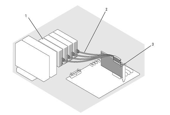
- If you are installing a SAS drive, connect the SAS interface cable to the hard drives and to the optional SAS controller card. (See Figure 3-10.)
Figure 3-9. Connecting SATA Hard Drives to the Integrated Drive Controller
|
1
|
SATA hard drive (up to four)
|
2
|
SATA interface cable
|
3
|
SATA_1 connector
|
|
4
|
SATA_0 connector
|
|
|
|
|
Figure 3-10. Connecting SATA Drives to a SAS Controller Card (SAS backplane not installed)
|
1
|
SATA hard drive (up to four)
|
2
|
SATA interface cable)
|
3
|
SAS controller card
|
- Ensure that all cables are firmly connected and arranged so that they will not catch on the computer
cover or block airflow inside the system.
- Close the system. See Closing the System.
- Stand the system upright.
- Reconnect the system to its electrical outlet and turn the system on, including any attached
peripherals.
- Partition and logically format the hard drive. See the operating system documentation for more
information.
- Install any required device drivers.
- Run the hard drive tests in the system diagnostics to determine whether the drive operates properly.
See Running the System Diagnostics.
If the drive is connected to a SATA RAID controller card, see the RAID controller card documentation for information on testing the controller.
If the drive is connected to a SAS controller card, run the SAS controller tests and the hard-drive tests in the system diagnostics. See Running the System Diagnostics
If the hard drive fails the hard-drive tests or does not operate properly, see Getting Help.
Removing a Hard Drive from a Lever-Release Drive Carrier
|
|
NOTICE: To prevent data loss, you must shut down the system before removing a drive carrier, unless a SAS controller is connected to the optional SAS backplane. See Hot-Plug SATA Hard Drives Using the SAS Backplane for information on hot-plug drive requirements and operation. |
The drive bays in a system with an optional SAS backplane board provides space for up to four optional lever-release hard drives. The hard drives plug into the SAS backplane board, which is connected to the controller card (see Figure 3-12). For instructions on installing the optional SAS backplane board, see Removing and Installing the Optional SAS Backplane Board.
- Turn off the system, including any attached peripherals, and disconnect the system from the electrical
outlet.
- Remove the bezel. See Removing the Bezel.
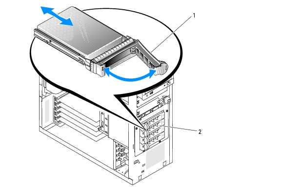
- Open the hard-drive carrier handle to release the drive. See Figure 3-11.
- Slide the hard drive out until it is free of the drive bay.
Figure 3-11. Removing or Installing a SCSI Hard-Drive Carrier
|
1
|
hard-drive carrier handle
|
2
|
lever-release drive carrier
|
|
|
Installing an Hard Drive in the Lever-Release Drive Carrier
- Turn off the system, including any attached peripherals, and disconnect the system from the electrical
outlet.
- Remove the bezel. See Removing the Bezel.
- Open the hard-drive carrier handle. See Figure 3-11.
|
|
NOTICE: Do not insert a hard-drive carrier and attempt to lock its handle next to a partially installed carrier. Doing so can damage the partially installed carrier's shield spring and make it unusable. Ensure that the adjacent drive carrier is fully installed. |
- Insert the hard-drive carrier into the drive bay. See Figure 3-11.
- Close the hard-drive carrier handle to lock it in place.
- Install the bezel. See Installing the Bezel.
- Reconnect the system to its electrical outlet and turn the system on, including any attached
peripherals.
- Install any required device drivers.
- Run the SAS controllers tests and the hard-drive tests in the system diagnostics. See Running the
System Diagnostics.
If the hard drive fails the hard-drive tests or does not operate properly, see Getting Help.
Hot-Plug SATA Hard Drives Using the SAS Backplane
If you are using the optional SAS backplane, the SATA hard drives you install are hot-pluggable if the backplane is attached directly to the SAS controller card on the system board (see Figure 3-13). For instructions on installing the optional SAS backplane board, see Removing and Installing the Optional SAS Backplane Board.
The SAS backplane supports up to four hot-plug hard drives connected to the optional SAS controller card. The SAS controller card must be connected to channel A on the optional SAS controller card, or port 0 on an optional RAID controller card. For instructions on installing the optional SAS backplane board, see Removing and Installing the Optional SAS Backplane Board.
Removing and Installing the Optional SAS Backplane Board
The optional SAS backplane board supports hot-plug SAS or SATA drives (if an optional SAS controller card is installed in the system).
|
|
CAUTION: Only trained service technicians are authorized to remove the system cover and access any of the components inside the system. Before performing any procedure, see your Product Information Guide for complete information about safety precautions, working inside the computer, and protecting against electrostatic discharge. |
- Turn off the system, including any attached peripherals, and disconnect the system from the electrical
outlet.
- Open the system. See Opening the System.
- Remove all existing hard drives from the hard drive bay. See Removing a Hard Drive from the Drive
Bay.
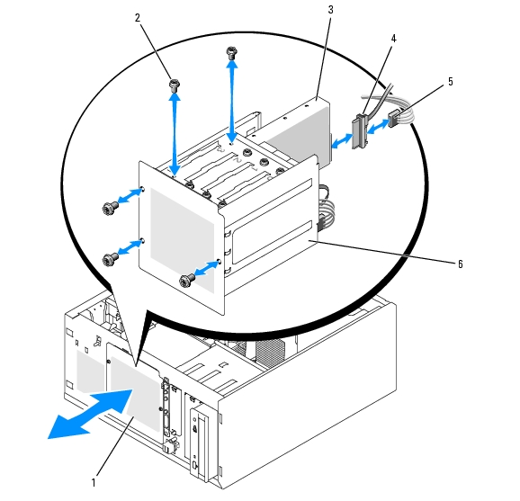
- Install the SAS backplane:
- Lower the backplane into the system and align the backplane with the retention hooks on the
drive bay, then fit the backplane over the retention hooks.
- Slide the backplane board toward the front fan about 12 mm (0.5 inch) until it clicks into place.
Figure 3-12. Installing the SAS Backplane Board
|
1
|
release tab
|
2
|
power connector
|
3
|
I2C connector
|
|
4
|
data cable
|
5
|
power cable
|
|
|
- Connect the power cable connector P3 to the power connector on the SAS backplane. See Figure 3-12.
- Connect the baseboard management controller (BMC) inter-IC (I2C) cable to the SAS backplane. See
Figure 3-12.
- Connect the other end of the BMC I2C cable to connector BP_I2C on the system board. See System
Board Connectors.
- If not already installed, install the SAS controller card.
See Installing an Expansion Card for instructions about installing the card.
- Connect the SAS data cable to the SAS controller card, and to the SAS interface connector on the
backplane. See Figure 3-13 and Figure 3-12.
- Close the system. See Closing the System.
- Stand the system upright.
- Install the hard drives into the hard-drive bay. See Figure 3-11.
- Reconnect the system to its electrical outlet and turn the system on, including any attached
peripherals.
- Install any required device drivers.
- Run the SAS controllers tests and the hard-drive tests in the system diagnostics. See Running the
System Diagnostics.
Installing SATA and SCSI hard drives in the same system is not supported.
Figure 3-13. SAS Backplane Connected to a SAS Controller Card
|
1
|
SAS backplane
|
2
|
SATA hard drive (up to four)
|
3
|
SAS interface cable
|
|
4
|
SAS controller card
|
|
|
|
|
Removing a Hot-Plug SAS or SATA Hard Drive
|
|
NOTICE: Not all operating systems support hot-plug drive installation. See the operating system documentation to confirm that the operating system supports this feature. |
- Remove the bezel. See Removing the Bezel."
- Take the hard drive offline and wait until the hard-drive indicator codes on the drive carrier signal that
the drive can be removed safely. See Table 1-5 for a list of hard-drive indicator codes.
If the drive has been online, the drive status indicator will blink green two times per second as the drive is powered down. When all indicators are off, the drive is ready for removal.
See your operating system documentation for more information on taking the hard drive offline.
- Remove the drive. See Removing a Hard Drive from a Lever-Release Drive Carrier.
Cooling Shroud
Removing the Cooling Shroud
|
|
CAUTION: Only trained service technicians are authorized to remove the system cover and access any of the components inside the system. Before performing any procedure, see your Product Information Guide for complete information about safety precautions, working inside the computer, and protecting against electrostatic discharge. |
- Turn off the system, including any attached peripherals, and disconnect the system from the electrical
outlet.
- Open the system. See Opening the System.
- Disconnect the power cables and hard-drive interface cable connectors from the SAS backplane (if
applicable) or hard drives.
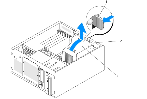
- Press the shroud release tab on the back panel toward the power supply. See Figure 3-14.
- Lift the cooling shroud out of the system. See Figure 3-14.
Figure 3-14. Removing the Cooling Shroud
|
1
|
shroud release tab
|
2
|
anchor tabs (2)
|
3
|
cooling shroud
|
Installing the Cooling Shroud
- Ensure that no tools or loose parts are left inside the system.
- Align the anchor tabs on the cooling shroud with the notches in the system chassis.
- Reposition the SAS or SATA cables and power cables so they do not obstruct the memory modules and
interfere with installing the cooling shroud.
- Gently lower the cooling shroud until the shroud release tab on the back panel snaps into place.
- Reconnect the power cable(s) to the SAS backplane (if applicable) or the hard drive(s).
Cooling Fans
The system includes the following cooling fans:
- Front system fan (only when configured with optional SAS or RAID controller cards)
- Back system fan
Removing the Front System Fan
|
|
CAUTION: Only trained service technicians are authorized to remove the system cover and access any of the components inside the system. Before performing any procedure, see your Product Information Guide for complete information about safety precautions, working inside the computer, and protecting against electrostatic discharge. |
Figure 3-15 illustrates the front system fan inside the system and the fan cable routing hole in the expansion-card guide bracket.
- Turn off the system, including any attached peripherals, and disconnect the system from the electrical
outlet.
- Open the system. See Opening the System.
- Disconnect the fan power cable from the FRONT_FAN connector on the system board. See System
Board Connectors.
Figure 3-15. Front System Fan Power Cable
|
1
|
expansion-card guide bracket
|
2
|
cable routing hole
|
3
|
fan power cable
|
|
4
|
release tabs (2)
|
|
|
|
|
- Squeeze the two release tabs on the top of the fan assembly and lift the fan assembly away from the
system. See Figure 3-15.
Installing the Front System Fan
|
|
CAUTION: Only trained service technicians are authorized to remove the system cover and access any of the components inside the system. Before performing any procedure, see your Product Information Guide for complete information about safety precautions, working inside the computer, and protecting against electrostatic discharge. |
- Insert the fan power cable through the cable routing hole in the expansion-card guide bracket. See
Figure 3-15.
- Align the fan assembly with the slots in the chassis and lower the assembly into the chassis. See
Figure 3-15.
- Pull the fan cable through the routing hole in the expansion-card guide bracket. See Figure 3-15.
- Connect the fan cable connector to the FRONT_FAN connector on the system board.
- Close the system. See Connecting Drives.
- Stand the system upright.
- Reconnect the system to its electrical outlet and turn the system on, including any attached
peripherals.
Removing the Back System Fan
|
|
CAUTION: Only trained service technicians are authorized to remove the system cover and access any of the components inside the system. Before performing any procedure, see your Product Information Guide for complete information about safety precautions, working inside the computer, and protecting against electrostatic discharge. |
- Turn off the system, including any attached peripherals, and disconnect the system from the electrical
outlet.
- Open the system. See Opening the System.
- Remove the cooling shroud. See Removing the Cooling Shroud.
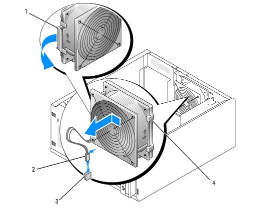
- Disconnect the fan cable from the BACK_FAN connector on the system board. To identify system
board connectors, see System Board Connectors.
- Pull the release tab on the fan assembly away from the back panel and slide the fan assembly about
0.63 cm (0.25 inch) toward the expansion-card slots. See Figure 3-16.
- Pull the fan assembly forward and lift the assembly out of the system. See Figure 3-16.
Figure 3-16. Removing the Back System Fan
|
1
|
release tab
|
2
|
fan cable connector
|
3
|
BACK_FAN connector
|
|
4
|
back system fan
|
|
|
|
|
Installing the Back System Fan
|
|
CAUTION: Only trained service technicians are authorized to remove the system cover and access any of the components inside the system. Before performing any procedure, see your Product Information Guide for complete information about safety precautions, working inside the computer, and protecting against electrostatic discharge. |
- Align the tabs on the fan bracket with the mounting holes in the back panel and slide the fan assembly
toward the power supply about 0.63 cm (0.25 inch) until the fan bracket release tab snaps into place.
See Figure 3-16.
- Connect the fan cable to the BACK_FAN connector on the system board.
To identify system board connectors, see System Board Connectors.
- Install the cooling shroud. See Installing the Cooling Shroud."
- Close the system. See Closing the System.
- Stand the system upright.
- Reconnect the system to its electrical outlet and turn the system on, including any attached
peripherals.
Power Supply
Removing the Power Supply
|
|
CAUTION: Only trained service technicians are authorized to remove the system cover and access any of the components inside the system. Before performing any procedure, see your Product Information Guide for complete information about safety precautions, working inside the computer, and protecting against electrostatic discharge. |
- Turn off the system and attached peripherals, and disconnect the system from the electrical outlet.
- Open the system. See Opening the System.
- Disconnect the DC power cables from the following components:
- POWER CONN connector on the backplane board (if applicable)
- PWR_CONN and 12V connectors on the system board
- Hard drives
- Diskette drive (if applicable)
- Optical drive (if applicable)
- Tape backup drive (if applicable)
- Remove the cooling shroud. See Removing the Cooling Shroud.
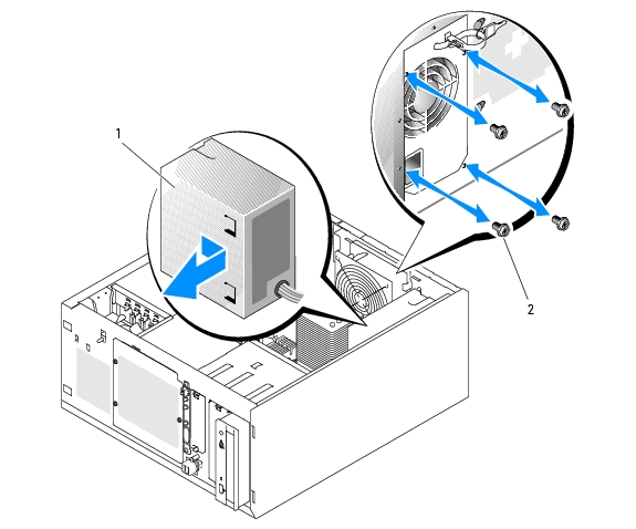
- Remove the four screws securing the power supply to the back panel. See Figure 3-17.
Figure 3-17. Removing the Power Supply
|
1
|
power supply
|
2
|
screws (4)
|
|
|
- Slide the power supply toward the front of the system, and then lift the power supply up and out of the
system.
Replacing the Power Supply
- Lower the power supply into the system and align the mounting holes with the holes on the back
panel.
- Install the four screws securing the power supply to the back panel.
- Install the cooling shroud. See Installing the Cooling Shroud.
- Connect the DC power cables to the following components:
- POWER CONN connector on the backplane board (if applicable)
- PWR_CONN and 12V connectors on the system board
- Hard drives or SAS backplane.
- Diskette drive (if applicable)
- Optical drive (if applicable)
- Tape backup drive (if applicable)
- Close the system. See Closing the System.
- Stand the system upright.
- Reconnect the system to its electrical outlet and turn the system on, including any attached
peripherals.
Expansion Cards
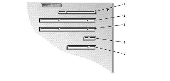
Your system supports up to five full-length expansion cards, installed in connectors on a riser card. The expansion slots are configured as follows:
- Slot 1 is a x8 lane-width PCI-Express expansion slot.
- Slot 2 is a x1 lane-width PCI-Express expansion slot.
- Slots 3 and 4 are 3.3-V, 64-bit, 133-MHz PCI-X expansion slots.
- Slot 5 is a 5-V, 32-bit, 33-MHz legacy PCI expansion slot.
Figure 3-18 shows the relative locations of the expansion-card slots.
|
|
NOTICE: If you install a RAC card, it must be installed in PCI slot SLOT_5. |
Figure 3-18. Expansion Slots
|
1
|
SLOT_5 - PCI 32-bit, 33-MHz (5-V)
|
2
|
SLOT_4 - PCI-X 64-bit, 133-MHz (3.3-V)
|
3
|
SLOT_3 - PCI-X 64-bit, 133-MHz (3.3-V)
|
|
4
|
SLOT_2 - x1 lane width PCI-Express
|
5
|
SLOT_1 - x8 lane width PCI-Express
|
|
|
Installing an Expansion Card
|
|
CAUTION: Only trained service technicians are authorized to remove the system cover and access any of the components inside the system. Before performing any procedure, see your Product Information Guide for complete information about safety precautions, working inside the computer, and protecting against electrostatic discharge. |
- Unpack the expansion card, and prepare it for installation.
For instructions, see the documentation that accompanied the card.
- Turn off the system, including any attached peripherals, and disconnect the system from the electrical
outlet.
- Open the system. See Opening the System.
- Remove the filler bracket from the expansion slot.
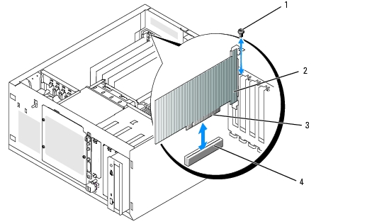
- Install the expansion card. See Figure 3-19.
- Position the expansion card so that the card-edge connector aligns with the expansion-card
connector on the system board.
- Insert the card-edge connector firmly into the expansion-card connector until the card is fully
seated.
- Install the screw that secures the expansion-card bracket to the back panel.
- Connect any cables that should be attached to the card.
See the documentation that accompanied the card for information about its cable connections.
- Close the system. See Closing the System.
- Stand the system upright.
- Reconnect the system to its electrical outlet and turn the system on, including any attached
peripherals.
- Install any device drivers required for the card as described in the documentation for the card.
Figure 3-19. Removing and Installing an Expansion Card
|
1
|
screw
|
2
|
expansion card
|
3
|
card-edge connector
|
|
4
|
expansion-card connector
|
|
|
|
|
Removing an Expansion Card
|
|
CAUTION: Only trained service technicians are authorized to remove the system cover and access any of the components inside the system. Before performing any procedure, see your Product Information Guide for complete information about safety precautions, working inside the computer, and protecting against electrostatic discharge. |
- Turn off the system, including any attached peripherals, and disconnect the system from the electrical
outlet.
- Open the system. See Opening the System.
- Disconnect any cables attached to the card.
- Remove the expansion card (see Figure 3-19):
- Remove the screw that secures the expansion-card bracket to the back panel.
- Grasp the expansion card by its top corners, and carefully remove it from the expansion-card
connector.
|
|
NOTICE: You must install a filler bracket over an empty expansion slot to maintain Federal Communications Commission (FCC) certification of the system. The brackets also help keep dust and dirt out of the system and aid in proper cooling and airflow inside the system. |
- If you are removing the card permanently, install a metal filler bracket over the empty expansion slot
opening and close the expansion-card latch.
- Close the system. See Closing the System.
- Stand the system upright.
- Reconnect the system to its electrical outlet and turn the system on, including any attached
peripherals.
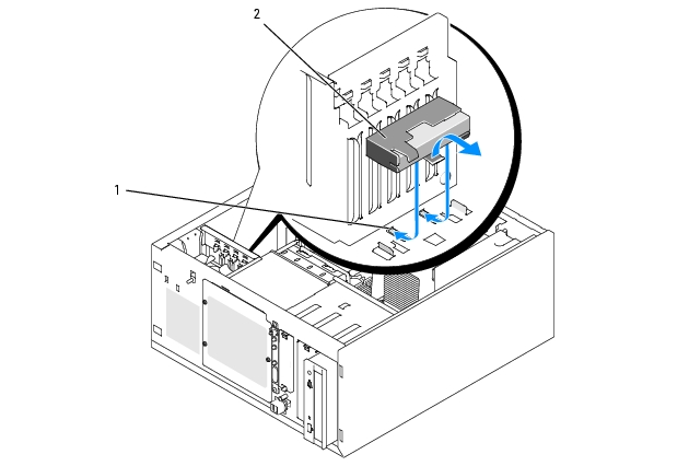
Replacing the SAS Controller Card Battery
- Disconnect the battery cable from the SAS controller card.
Figure 3-20. Replacing the SAS Controller Card Battery
|
1
|
chassis notches
|
2
|
battery/battery holder
|
|
|
- Remove the battery and battery holder from the system chassis. See Figure 3-20.
- Insert the new battery into the battery bay, ensuring that the battery is aligned and fully seated into the
slots.
- Connect the battery cable to the SAS controller card.
Memory
You can upgrade your system memory to a maximum of 8 GB by installing combinations of 512-MB, 1-GB, and 2-GB unbuffered ECC DDRII SDRAM 533- or 667-MHz memory modules. The system memory is located on the system board adjacent to the power supply connectors. See System Board Connectors. The memory module sockets are arranged in two banks on two channels (A and B). The memory module banks are identified as follows:
- Bank 1: DIMM1_A and DIMM1_B
- Bank 2: DIMM2_A and DIMM2_B
General Memory Module Installation Guidelines
- If only one memory module is installed, it must be installed in socket DIMM1_A.
- If two or more memory modules are installed, they must be installed in pairs of matched memory size, speed, and technology.
Table 3-2 shows examples of different memory configurations.
Table 3-2. Sample Memory Configurations
|
Total Memory
|
DIMM1_A
|
DIMM2_A
|
DIMM1_B
|
DIMM2_B
|
|---|
512 MB
| 512 MB
| None
| None
| None
|
1 GB
| 512 MB
| None
| 512 MB
| None
|
1 GB
| 1 GB
| None
| None
| None
|
2 GB
| 512 MB
| 512 MB
| 512 MB
| 512 MB
|
2 GB
| 1 GB
| None
| 1 GB
| None
|
3 GB
| 1 GB
| 512 MB
| 1 GB
| 512 MB
|
4 GB
| 1 GB
| 1 GB
| 1 GB
| 1 GB
|
4 GB
| 2 GB
| None
| 2 GB
| None
|
5 GB
| 2 GB
| 512 MB
| 2 GB
| 512 MB
|
6 GB
| 2 GB
| 1 GB
| 2 GB
| 1 GB
|
8 GB
| 2 GB
| 2 GB
| 2 GB
| 2 GB
|
Installing Memory Modules
|
|
CAUTION: Only trained service technicians are authorized to remove the system cover and access any of the components inside the system. Before performing any procedure, see your Product Information Guide for complete information about safety precautions, working inside the computer, and protecting against electrostatic discharge. |
- Turn off the system, including any attached peripherals, and disconnect the system from the electrical
outlet.
- Open the system. See Opening the System.
- Locate the memory module sockets. See System Board Connectors.
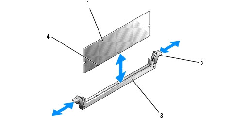
- Press the ejectors on the memory module socket down and out, as shown in Figure 3-21, to allow the
memory module to be inserted into the socket.
Figure 3-21. Installing and Removing a Memory Module
|
1
|
memory module
|
2
|
memory module socket ejectors (2)
|
3
|
socket
|
|
4
|
alignment keys (2)
|
|
|
|
|
- Align the memory module's edge connector with the alignment keys on the memory module socket,
and insert the memory module in the socket.
|
|
NOTE: The memory module socket has alignment keys that ensure correct insertion of the memory module in the socket. |
- Press down on the memory module with your thumbs while pulling up on the ejectors with your index
fingers to lock the memory module into the socket.
When the memory module is properly seated in the socket, the ejectors on the memory module socket align with the ejectors on the other sockets that have memory modules installed.
- Repeat this procedure to install the remaining memory modules. See Table 3-2 for sample memory
configurations.
- Close the system. See Closing the System.
- Stand the system upright.
- Reconnect the system to its electrical outlet and turn the system on, including any attached
peripherals.
- (Optional) Press <F2> to enter the System Setup program, and check the System Memory setting on
the main System Setup screen.
The system should have already changed the value to reflect the newly installed memory.
- If the value is incorrect, one or more of the memory modules may not be installed properly. Repeat step
1 through step 11 of this procedure, checking to ensure that the memory modules are firmly seated in
their sockets.
- Run the system memory test in the system diagnostics. See Running the System Diagnostics.
Removing Memory Modules
|
|
CAUTION: Only trained service technicians are authorized to remove the system cover and access any of the components inside the system. Before performing any procedure, see your Product Information Guide for complete information about safety precautions, working inside the computer, and protecting against electrostatic discharge. |
- Turn off the system, including any attached peripherals, and disconnect the system from the electrical
outlet.
- Open the system. See Opening the System.
- Locate the memory module sockets. See System Board Connectors.
- Press down and out on the ejectors on each end of the socket until the memory module pops out of the
socket. See Figure 3-21.
- Close the system. See Closing the System.
- Stand the system upright.
Microprocessor
You can upgrade the system processor to take advantage of future options in speed and functionality.
A processor upgrade kit contains the following items:
- Processor
- Thermal grease packet and/or a replacement heat sink
If your kit does not include a replacement heat sink, you must reuse the processor heat sink currently in your system.
|
|
NOTICE: If your upgrade kit included a thermal grease packet, you must use the thermal grease as instructed to ensure the proper thermal operating condition for the processor. Failure to do so will result in damage to your system. |
Removing the Processor
|
|
CAUTION: Only trained service technicians are authorized to remove the system cover and access any of the components inside the system. Before performing any procedure, see your Product Information Guide for complete information about safety precautions, working inside the computer, and protecting against electrostatic discharge. |
- Turn off the system, including any attached peripherals, and disconnect the system from the electrical
outlet.
- Open the system. See Opening the System.
- Remove the cooling shroud. See Removing the Cooling Shroud.
|
|
NOTICE: Never remove the heat sink from a processor unless you intend to remove the processor. The heat sink is necessary to maintain proper thermal conditions. |
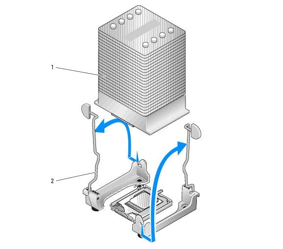
- Remove the heat sink. See Figure 3-22.
- Open one securing clip by pressing the end of the clip down and away from the retention module
until it clears the securing tab on the retention module, and then lift the clip up.
- Repeat step a for the remaining securing clip.
- Rotate the heat sink slightly and then lift the heat sink off the processor. Do not pry the processor
off the heat sink.
- If you are reusing the heat sink with the new processor, clean the contact side of the heat sink and
set it aside for use later in the processor installation procedure.
Figure 3-22. Removing the Heat Sink
|
1
|
heat sink
|
2
|
securing clips (2)
|
|
|
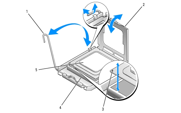
- Press down on the processor socket release lever, then pull the release lever upward to the fully open
position. See Figure 3-23.
- Open the processor cover. See Figure 3-23.
- Lift the processor vertically out of the socket. Leave the processor cover and release lever in the open
position so that the socket is ready for the new processor. See Figure 3-23.
Figure 3-23. Removing/Replacing the Processor
|
1
|
processor socket release lever
|
2
|
processor cover
|
3
|
pin-1 locators
|
|
4
|
processor socket
|
5
|
processor
|
|
|
Installing a Processor
|
|
CAUTION: Only trained service technicians are authorized to remove the system cover and access any of the components inside the system. Before performing any procedure, see your Product Information Guide for complete information about safety precautions, working inside the computer, and protecting against electrostatic discharge. |
- Unpack the new processor and heat sink, if provided.
- Ensure that the processor socket release lever is in the fully open position.
- Align the pin 1 corners of the processor and socket. See Figure 3-23.
|
|
NOTICE: You must position the processor correctly in the socket to avoid damaging the processor and the system board when you turn on the system. Be careful not to touch or bend the pins on the socket. |
- Set the processor lightly in the socket and ensure that the processor is level in the socket. When the
processor is positioned correctly, press it gently to seat it in the socket.
- Close the processor cover.
- Rotate the release lever back down until it snaps into place, securing the processor cover.
|
|
NOTICE: Do not operate the system without the heat sink installed. The heat sink is required to maintain proper thermal conditions. |
- Prepare the heat sink for installation:
- If you are reusing the heat sink from the previous processor, ensure that the contact side (bottom) of the heat sink is clean, open the thermal grease packet, and apply thermal grease to the bottom of the heat sink.
- If you received a replacement heat sink, remove the protective sheet from the thermal grease layer that is pre-applied to the bottom of the heat sink.
- Lower the heat sink onto the processor. See Figure 3-22.
- Secure the heat sink to the retention module.
- Gently press down on the heat sink and then press one securing clip to secure it.
- Repeat step a for the remaining securing clip.
- Ensure that the back fan connector is connected to the BACK_FAN connector on the system board.
See System Board Connectors.
- Install the cooling shroud. See Installing the Cooling Shroud.
- Close the system. See Closing the System.
- Stand the system upright.
- Reconnect the system to its electrical outlet and turn the system on, including any attached
peripherals.
- Enter the System Setup program, and ensure that the processor options match the new system
configuration. See Using the System Setup Program.
As the system boots, it detects the presence of the new processor and automatically changes the system configuration information in the System Setup program. A message similar to the following appears:
One 2.8 GHz Processor, Processor Bus: 533 MHz, L2 cache 256 KB
- Confirm that the top line of the system data area in the System Setup program correctly identifies the
installed processor. See Using the System Setup Program.
- Exit the System Setup program.
- Ensure that your system is running the latest BIOS version.
You can download the latest BIOS version from the Dell Support website located at support.dell.com
- Run the system diagnostics to verify that the new processor is operating correctly.
See Running the System Diagnostics for information on running the diagnostics and troubleshooting any problems that may occur.
Installing a RAC Card
|
|
CAUTION: Only trained service technicians are authorized to remove the system cover and access any of the components inside the system. Before performing any procedure, see your Product Information Guide for complete information about safety precautions, working inside the computer, and protecting against electrostatic discharge. |
- Turn off the system, including any attached peripherals, and disconnect the system from the electrical
outlet.
- Open the system. See Opening the System.
- Install the RAC card in PCI expansion slot SLOT_5.
See Installing an Expansion Card for information on installing the card.
- Connect the cable from the RAC card to connector RAC_CONN on the system board. See System
Board Connectors.
- Close the system. See Closing the System.
- Stand the system upright.
- Reconnect the system to its electrical outlet and turn the system on, including any attached
peripherals.
- Enter the System Setup program and verify that the setting for the RAC card has changed to reflect
the presence of the card. See Using the System Setup Program.
See the RAC card documentation for information on configuring and using the RAC card.
System Battery
Replacing the System Battery
|
|
CAUTION: Only trained service technicians are authorized to remove the system cover and access any of the components inside the system. Before performing any procedure, see your Product Information Guide for complete information about safety precautions, working inside the computer, and protecting against electrostatic discharge. |
- Enter the System Setup program and record the option settings on the System Setup screens.
See Using the System Setup Program.
- Turn off the system, including any attached peripherals, and disconnect the system from the electrical
outlet.
- Open the system. See Opening the System.
- Remove the system battery. See System Board Connectors for the battery socket location on the
system board.
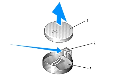
- Pull the latch away from the battery. See Figure 3-24.
- Lift the battery out of the battery socket.
|
|
NOTICE: You must install the new system battery with the side labeled "+" facing up. See Figure 3-24. |
Figure 3-24. Removing the System Battery
|
1
|
system battery
|
2
|
latch
|
3
|
battery socket
|
- To install the new system battery, hold the battery with the side labeled "+" facing up, and then press
the battery straight down into the battery socket until the latch snaps into place over the edge of the
battery. See Figure 3-24.
- Close the system. See Closing the System.
- Stand the system upright.
- Reconnect the system to its electrical outlet and turn the system on, including any attached
peripherals.
- Enter the System Setup program to confirm that the battery operates properly.
- From the main screen, select System Time to enter the correct time and date.
- Re-enter any system configuration information that is no longer displayed on the System Setup
screens, and then exit the System Setup program.
- To test the newly installed battery, see Troubleshooting the System Battery.
Front I/O Panel (Service-Only Parts Procedure)
Removing the Control Panel Assembly and Chassis-Intrusion Switch
|
|
CAUTION: Only trained service technicians are authorized to remove the system cover and access any of the components inside the system. Before performing any procedure, see your Product Information Guide for complete information about safety precautions, working inside the computer, and protecting against electrostatic discharge. |
- Turn off the system and attached peripherals, and disconnect the system from the electrical outlet.
- Open the system. See Opening the System.
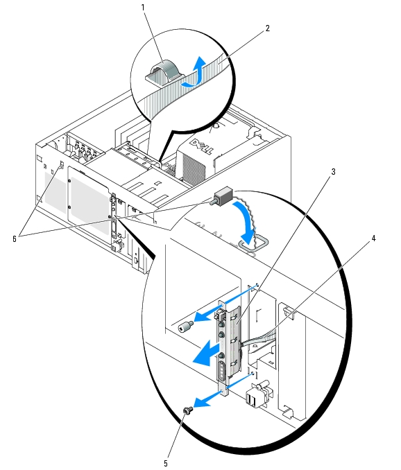
- Disconnect the control panel assembly cable from the FRONT_PANEL connector on the system board
and remove the assembly cable from its guide bracket. See Figure 3-25.
- Slide the chassis-intrusion switch upward and lift it out of its slot in the front of the chassis. Then,
remove the chassis-intrusion cable from its three holding clips underneath the front lip of the system
chassis.
- Using a #2 Phillips screwdriver, remove the two screws that secure the control panel assembly to the
chassis. See Figure 3-25.
- Lift the control panel assembly and the attached chassis-intrusion switch away from the system. See
Figure 3-25.
Figure 3-25. Removing the Control Panel Assembly
|
1
|
assembly cable guide bracket
|
2
|
chassis floor
|
3
|
control panel assembly
|
|
4
|
control panel assembly cable
|
5
|
mounting screws (2)
|
6
|
chassis-intrusion switch
|
Installing the Control Panel Assembly
- Insert the control panel assembly cable and chassis-intrusion switch through the front of the system.
- Thread the chassis-intrusion switch upward through the opening above the control panel slot.
- Connect the control panel assembly cable connector to the FRONT_PANEL connector on the system
board and insert the cable in its guide bracket.
- Guide the chassis-intrusion switch cable through the three holding clips underneath the front lip of
the system chassis.
- Insert the chassis-intrusion switch into its slot in the front of the chassis, then slide the switch down
into place.
- Using a #2 Phillips screwdriver, install the screws that secure the control panel assembly to the chassis.
See Figure 3-25.
- Close the system. See Closing the System.
- Stand the system upright.
- Reconnect the system to its electrical outlet and turn the system on, including any attached
peripherals.
System Board (Service-Only Parts Procedure)
The system board and system board tray are removed and replaced as a single assembly.
|
|
CAUTION: Only trained service technicians are authorized to remove the system cover and access any of the components inside the system. Before performing any procedure, see your Product Information Guide for complete information about safety precautions, working inside the computer, and protecting against electrostatic discharge. |
|
|
CAUTION: The processor heat sink can get hot during operation. To avoid burns, ensure that the system has sufficient time to cool before removing the system board. |
Removing the System Board
- Turn off the system and attached peripherals, and disconnect the system from the electrical outlet.
- Disconnect the cables to the I/O connectors on the back panel.
- Open the system. See Opening the System.
- Disconnect the two power cables from connectors PWR_CONN and 12V on the system board.
- Remove the cooling shroud. See Removing the Cooling Shroud.
- If the system has cabled SAS drives or SATA drives, note the relative location of the interface cable
connections between the system board and the drives, so you can reconnect them in the proper
sequence.
- Disconnect the SAS or SATA interface cable(s) connected to the system board or optional hard-drive
controller card.
- Disconnect the power cable(s) connected to the hard drives in the drive bay, or to the optional SAS
backplane.
- Remove the screws securing the drive bay and remove the bay from the system.
- Disconnect all remaining cables attached to the connectors on the system board:
- Optical-drive interface cable (PRIMARY_IDE connector)
- Diskette-drive cable (FDD connector)
- Control panel cable (FRONT_PANEL connector)
- Front fan cable (FRONT_FAN connector)
- Back fan cable (BACK_FAN connector)
- Any other cables attached to the system board, after recording their locations.
- Remove the back fan. See Removing the Back System Fan in "Installing System Components."
- Remove all PCI expansion cards from the expansion slots. See Removing an Expansion Card.
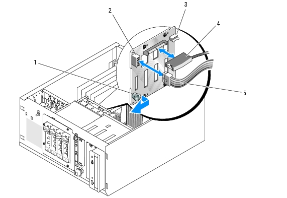
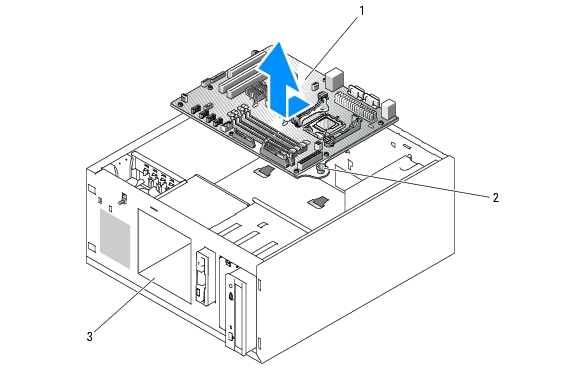
- Pull up on the system board plunger and slide the system board toward the front of the chassis about
2.5 cm (1 inch). See Figure 3-26.
- Carefully lift the system board up and out of the chassis. See Figure 3-26.
Figure 3-26. Removing the System Board
|
1
|
system board
|
2
|
plunger
|
3
|
drive bay
|
Installing the System Board
- Unpack the new system board.
- Ensure that the system board jumpers are set the same as on the board that you just removed, and
change the settings if necessary. See System Board Jumpers.
- Remove the memory modules from the original system board and transfer them to the new board,
being careful to install the memory modules in the same locations.
See Installing Memory Modules.
- Remove the processor from the original system board. See Removing the Processor.
- Reinstall the processor and heat sink on the new system board. See Installing a Processor.
- Making sure that no cables are trapped beneath the system board tray, lower the new system board into
the chassis.
- Position the system board in place and gently press down on the board until the plunger locks.
- Install the back fan and connect the fan cable to the BACK_FAN connector on the system board. See
Installing the Back System Fan.
- Connect the following cables to the system board. See System Board Connectors.
- Optical-drive interface cable (PRIMARY_IDE connector)
- Diskette-drive cable (FDD connector)
- Control panel cable (FRONT_PANEL connector)
- Front fan cable (FRONT_FAN connector)
- Install all expansion cards and connect any interface cables to the appropriate components in the
system. See Installing an Expansion Card.
- Reinstall the drive bay and secure it with the four Phillips screws. See Installing a Hard Drive in the
Drive Bay.
- Reconnect the SAS or SATA interface cable(s) to the system board or optional hard-drive controller
card.
Ensure that you reattach the interface cables in their original locations.
- Reconnect the power cables to the hard drives in the drive bay, or to the optional SAS backplane.
- Replace the cooling shroud. See Installing the Cooling Shroud.
- Connect the two power cables to connectors PWR_CONN and 12V on the system board.
- Carefully check for any remaining cables or components that are not installed or are improperly seated
in their connectors on the system board.
- Close the system. See Closing the System.
- Stand the system upright.
- Reconnect the cables to the I/O connectors on the system back panel.
- Reconnect the system to its electrical outlet and turn the system on, including any attached
peripherals.
Back to Contents Page