Back to Contents Page
Installing System Components
Dell™ PowerEdge™ 850 Systems Installation and Troubleshooting Guide
 Cooling Shroud
System Battery
Fan Assembly
PCI Fan Module
Power Supply
Expansion Cards
Riser Card
System Memory
Processor
This section describes how to install the following system components:
- Cooling shroud
- System battery
- Fan assembly
- Power supply
- Expansion cards
- Riser card
- System memory
- Processor
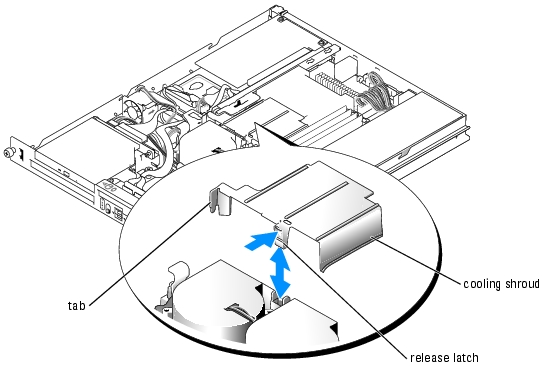
Cooling Shroud
The cooling shroud covers the processor and system battery. The shroud also directs air flow to the expansion cards and system memory.
Removing the Cooling Shroud

|
CAUTION: Only trained service technicians are authorized to remove the system cover and access any of the components inside the system. Before performing any procedure, see your Product Information Guide for complete information about safety precautions, working inside the computer and protecting against electrostatic discharge. |
- Open the system. See "Opening the System" in "Troubleshooting Your System."
- While grasping the cooling shroud, press the release latch and lift the shroud away from the
fan assembly. See Figure 5-1.
- Remove the cooling shroud.
Figure 5-1. Installing and Removing the Cooling Shroud
Installing the Cooling Shroud
- Insert the tab on the side of the cooling shroud and the release latch into the fan assembly.
See Figure 5-1.
- Push the cooling shroud down until the release latch snaps into place, securing the shroud to
the fan assembly.
- Close the system. See "Closing the System" in "Troubleshooting Your System."
System Battery
Replacing the System Battery
|
|
CAUTION: Only trained service technicians are authorized to remove the system cover and access any of the components inside the system. Before performing any procedure, see your Product Information Guide for complete information about safety precautions, working inside the computer and protecting against electrostatic discharge. |
- Enter the System Setup program and, if possible, make a printed copy of the System Setup
screens.
See "Using the System Setup Program" in the User's Guide.
- Open the system. See "Opening the System" in "Troubleshooting Your System."
- Remove the cooling shroud. See "Removing the Cooling Shroud."
- Remove the riser card. See "Removing the Riser Card."
- Locate the battery on the system board. See Figure A-3 for the battery location.
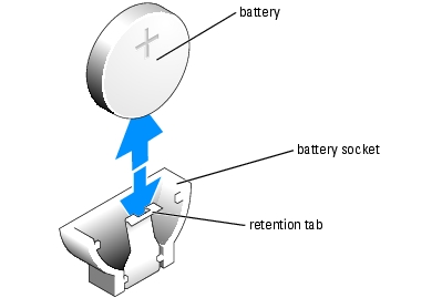
- Grasp the battery with your fingers and pull it out of the battery socket. See Figure 5-2.
- Push the new battery into the battery socket as shown in Figure 5-2.

|
NOTE: The side of the battery labeled "+" must face toward the open side of the battery socket. |
Figure 5-2. Replacing the Battery
- Reinstall the riser card. See "Installing the Riser Card."
- Install the cooling shroud. See "Installing the Cooling Shroud."
- Close the system. See "Closing the System" in "Troubleshooting Your System."
- Enter the System Setup program to confirm that the battery operates properly.
- From the main screen, select System Time to enter the correct time and date.
Also, re-enter any system configuration information that is no longer displayed on the System Setup screens, and then exit the System Setup program.
- To test the newly installed battery, see "Troubleshooting the System Battery" in
"Troubleshooting Your System."
Fan Assembly
The fan assembly contains two fans and provides cooling for the processor and memory modules.
Removing the Fan Assembly
|
|
CAUTION: Only trained service technicians are authorized to remove the system cover and access any of the components inside the system. Before performing any procedure, see your Product Information Guide for complete information about safety precautions, working inside the computer and protecting against electrostatic discharge. |
- Open the system. See "Opening the System" in "Troubleshooting Your System."
- Remove the cooling shroud. See "Removing the Cooling Shroud."
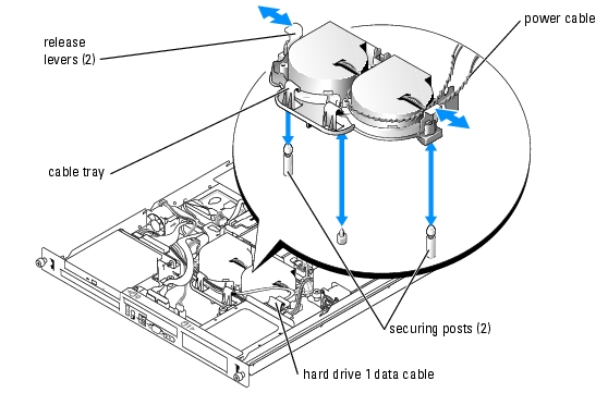
- Disconnect the fan assembly's power cable from the system board. See Figure 5-3.
- Disconnect the PCI fan cable from the fan assembly connector, if present.
- Remove the data cable from hard drive 1 if installed. See Figure 5-3.
- Pull the cables out of the fan assembly's cable tray. See Figure 5-3.
- While pressing the two release levers on the fan assembly, lift the fan assembly off of the two
securing posts and out of the chassis. See Figure 5-3.
Figure 5-3. Installing and Removing the Fan Assembly
Installing the Fan Assembly
- Align the holes in the fan assembly with the two fan assembly securing posts. See Figure 5-3.
- Lower the fan assembly until the release levers snap onto the securing posts.
- Route the cables in the fan assembly cable tray. See Figure 5-3.
- Reconnect the hard drive 1 data cable to the hard drive. See Figure 5-3.
- Reconnect the PCI fan cable to the fan assembly connector, if applicable.
- Reconnect the fan assembly power cable to the system board.
- Install the cooling shroud. See "Installing the Cooling Shroud."
- Close the system. See "Closing the System" in "Troubleshooting Your System."
PCI Fan Module
The PCI fan module provides cooling for the expansion cards.
Removing the PCI Fan Module
|
|
CAUTION: Many repairs may only be done by a certified service technician. You should only perform troubleshooting and simple repairs as authorized in your product documentation, or as directed by the online or telephone service and support team. Damage due to servicing that is not authorized by Dell is not covered by your warranty. Read and follow the safety instructions that came with the product. |
- Open the system. See "Opening the System" in "Troubleshooting Your System."
- Disconnect the fan module's power cable. Depending on your system, this connector may be
on the fan assembly cable or the daughter card.
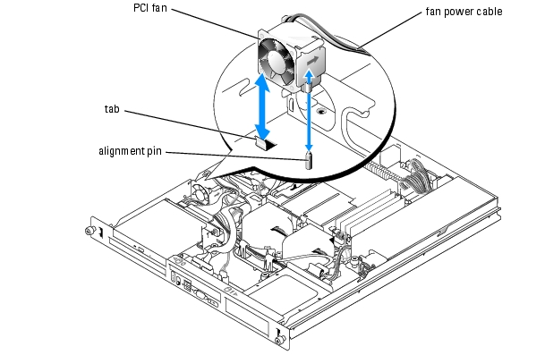
- Gently pull the fan module up and away from the alignment pin on the chassis, and remove
the fan module from the system. See Figure 5-4.
Figure 5-4. Installing and Removing the PCI Fan Module
Installing the PCI Fan Module
- With the fan power cable facing towards the rear of the system, align the fan module
alignment hole with the alignment pin on the chassis. See Figure 5-4.
- Install the PCI fan module against the tab and atop the alignment pin on the system chassis.
- Reconnect the fan module's power cable to the connector on the fan assembly or daughter
card.
- Close the system. See "Closing the System" in "Troubleshooting Your System."
Power Supply
The system supports a single nonredundant power supply.
Removing the Power Supply
|
|
CAUTION: Only trained service technicians are authorized to remove the system cover and access any of the components inside the system. Before performing any procedure, see your Product Information Guide for complete information about safety precautions, working inside the computer and protecting against electrostatic discharge. |
- Open the system. See "Opening the System" in "Troubleshooting Your System."
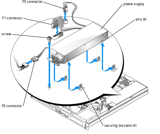
- Disconnect the following power supply cables:
- P3 from the hard drive cable harness
- P2 from system board connector 12V
- P1 from system board connector PWR_CONN
- Using a #2 Phillips screwdriver, remove the screw at the front of the power supply that secures
the power supply to the chassis. See Figure 5-5.
- Slide the power supply forward and lift straight up to remove the power supply from the
chassis.
Figure 5-5. Installing and Removing the Power Supply
Installing the Power Supply
- Lower the power supply into the chassis and slide it backward until the four pins on the power
supply are engaged into the securing brackets.
- Using a #2 Phillips screwdriver, install the screw at the front of the power supply that secures
the power supply to the chassis.
- Connect the following power supply cables:
- P3 to the hard drive cable harness
- P2 to the system board connector 12V
- P1 to the system board connector PWR_CONN
- Close the system. See "Closing the System" in "Troubleshooting Your System."
Expansion Cards
The system is available with an optional PCIe riser card or PCI-X/PCIe riser card. The PCIe riser card provides one PCIe x4-lane expansion slot and one PCIe x8-lane expansion slot, and the PCI-X/PCIe riser card provides one PCI-X expansion slot and one PCIe x8-lane expansion slot. If you are installing a remote access controller card, it must be installed in the upper slot of a PCI-X/PCIe riser card. See "Riser Card Connectors" in "Jumpers, Switches, and Connectors" for the locations of the expansion-card slots on the two types of riser cards.
Installing an Expansion Card
|
|
CAUTION: Only trained service technicians are authorized to remove the system cover and access any of the components inside the system. Before performing any procedure, see your Product Information Guide for complete information about safety precautions, working inside the computer and protecting against electrostatic discharge. |
- Open the system. See "Opening the System" in "Troubleshooting Your System."
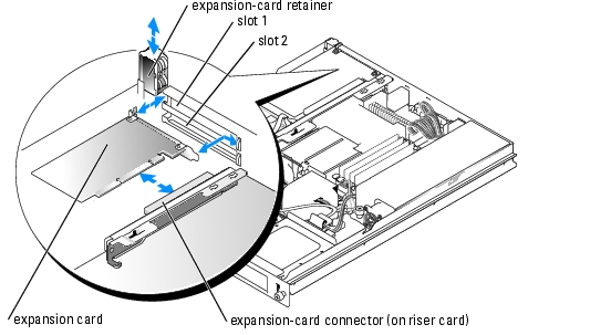
- Remove the expansion-card retainer adjacent to the expansion card slots. See Figure 5-6.
- Remove the filler bracket on the slot you will be using.
|
|
NOTE: Keep this bracket if you need to remove the expansion card. Filler brackets must be installed over empty expansion card slots to maintain Federal Communications Commission (FCC) certification of the system. The brackets also keep dust and dirt out of the system and aid in proper cooling and airflow inside the system. |
- Insert the expansion card firmly into the expansion-card connector on the riser card until the
card is fully seated.
|
|
NOTE: Ensure that the expansion-card bracket is also inserted into the securing slot on the chassis's back panel. |
- Replace the expansion-card retainer. See Figure 5-6.
- Connect any internal or external cable(s) to the expansion card.
|
|
NOTE: You may need to remove the riser card in order to install certain expansion cards with internal connectors. See "Riser Card." |
- Close the system. See "Closing the System" in "Troubleshooting Your System."
Figure 5-6. Installing and Removing Expansion Cards
Removing an Expansion Card
|
|
CAUTION: Only trained service technicians are authorized to remove the system cover and access any of the components inside the system. Before performing any procedure, see your Product Information Guide for complete information about safety precautions, working inside the computer and protecting against electrostatic discharge. |
- Open the system. See "Opening the System" in "Troubleshooting Your System."
- Disconnect any internal or external cable(s) that are connected to the expansion card.
- Lift the expansion-card retainer adjacent to the PCI slots. See Figure 5-6.
- Grasp the expansion card and carefully pull it away from the expansion-card connector.
If you are removing a SCSI controller card, disconnect the cables from the card that connects to the SCSI hard drives.
- If you are permanently removing the card, replace the metal filler bracket over the empty
card-slot opening.
|
|
NOTE: Filler brackets must be installed over empty expansion-card slots to maintain FCC certification of the system. The brackets also keep dust and dirt out of the system and aid in proper cooling and airflow inside the system. |
- Replace the expansion-card retainer.
- Close the system. See "Closing the System" in "Troubleshooting Your System."
Riser Card
The riser card provides two expansion-card slots. See "Expansion Cards" for detailed information on the expansion-card slots.
Removing the Riser Card
|
|
CAUTION: Only trained service technicians are authorized to remove the system cover and access any of the components inside the system. Before performing any procedure, see your Product Information Guide for complete information about safety precautions, working inside the computer and protecting against electrostatic discharge. |
- Open the system. See "Opening the System" in "Troubleshooting Your System."
- Remove any expansion card(s). See "Removing an Expansion Card."
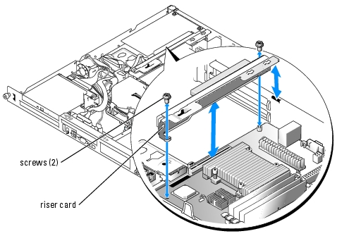
- Using a #2 Phillips screwdriver, remove the two screws that secure the riser card to the
chassis. See Figure 5-7.
- Lift the riser card straight up and remove the riser card from the system.
Figure 5-7. Installing and Removing the Riser Card
Installing the Riser Card
|
|
CAUTION: Only trained service technicians are authorized to remove the system cover and access any of the components inside the system. Before performing any procedure, see your Product Information Guide for complete information about safety precautions, working inside the computer and protecting against electrostatic discharge. |
- Insert the riser card firmly into the riser card connector on the system board until the riser
card is fully seated.
- Using a #2 Phillips screwdriver, install the two screws that secure the riser card to the system
board.
- Install any expansion card(s). See "Installing an Expansion Card."
- Close the system. See "Closing the System" in "Troubleshooting Your System."
System Memory
The four memory module sockets are located on the system board adjacent to the power supply and can accommodate 256 MB to 8 GB of unbuffered ECC PC-3200 (DDR2 533) memory. See Figure A-3 for the location of the memory module sockets.
You can upgrade the system memory by installing combinations of 256-MB, 512-MB, 1-GB, and 2-GB unbuffered memory modules. If you receive an error message stating that maximum memory has been exceeded, see "Indicators, Messages, and Codes" for more information. You can purchase memory upgrade kits from Dell.
|
|
NOTE: The memory modules must be PC-3200 compliant. |
Memory Module Installation Guidelines
The memory module sockets are arranged in banks (1 and 2) on two channels (A and B). The memory module banks must be installed in identical pairs.
The memory module banks are identified as follows:
Bank 1: DIMM1_A and DIMM1_B
Bank 2: DIMM2_A and DIMM2_B
For example, if socket DIMM1_A contains a 256-MB memory module, then socket DIMM1_B must contain a 256-MB memory module.
Table 5-1 shows examples of different memory configurations, based on the following guidelines:
- If only one memory module is installed, it must be installed in the DIMM1_A socket.
- A bank must contain identical memory modules.
- Install the memory modules in bank 1 (DIMM1_x) before installing memory modules in bank 2 (DIMM2_x).
- Installing three memory modules is not supported.
Table 5-1. Sample Memory Module Configurations
|
Total Memory
|
DIMM1_A
|
DIMM2_A
|
DIMM1_B
|
DIMM2_B
|
|---|
256 MB
| 256 MB
| None
| None
| None
|
512 MB
| 256 MB
| None
| 256 MB
| None
|
512 MB
| 512 MB
| None
| None
| None
|
1 GB
| 256 MB
| 256 MB
| 256 MB
| 256 MB
|
1 GB
| 512 MB
| None
| 512 MB
| None
|
1.5 GB
| 512 MB
| 256 MB
| 512 MB
| 256 MB
|
2 GB
| 512 MB
| 512 MB
| 512 MB
| 512 MB
|
2 GB
| 1 GB
| None
| 1 GB
| None
|
3 GB
| 1 GB
| 512 MB
| 1 GB
| 512 MB
|
4 GB
| 1 GB
| 1 GB
| 1 GB
| 1 GB
|
4 GB
| 2 GB
| None
| 2 GB
| None
|
5 GB
| 2 GB
| 512 MB
| 2 GB
| 512 MB
|
6 GB
| 2 GB
| 1 GB
| 2 GB
| 1 GB
|
8 GB
| 2 GB
| 2 GB
| 2 GB
| 2 GB
|
Installing Memory Modules
|
|
CAUTION: Only trained service technicians are authorized to remove the system cover and access any of the components inside the system. Before performing any procedure, see your Product Information Guide for complete information about safety precautions, working inside the computer and protecting against electrostatic discharge. |
- Open the system. See "Opening the System" in "Troubleshooting Your System."
- Locate the memory module sockets. See Figure A-3.
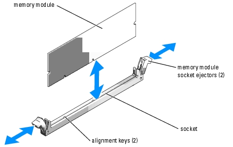
- Press the ejectors on the memory module socket down and out, as shown in Figure 5-8, to
allow the memory module to be inserted into the socket.
- Align the memory module's edge connector with the alignment keys of the memory module
socket, and insert the memory module in the socket.
|
|
NOTE: The memory module socket has two alignment keys that allow you to install the memory module in the socket in only one way. |
- Press down on the memory module with your thumbs while pulling up on the ejectors with
your index fingers to lock the memory module into the socket.
When the memory module is properly seated in the socket, the ejectors on the memory module socket align with the ejectors on the other sockets that have memory modules installed.
- Repeat step 2 through step 5 of this procedure to install the remaining memory modules. See
Table 5-1 for valid memory configurations.
- Close the system. See "Closing the System" in "Troubleshooting Your System."
- (Optional) Press <F2> to enter the System Setup program, and check the System Memory
setting on the main System Setup screen.
The system should have already changed the value to reflect the newly installed memory.
- If the value is incorrect, one or more of the memory modules may not be installed properly.
Repeat step 1 through step 8 of this procedure, checking to ensure that the memory modules
are firmly seated in their sockets.
- Run the system memory test in the system diagnostics. See "Running the System
Diagnostics."
Figure 5-8. Installing and Removing a Memory Module
Removing Memory Modules
|
|
CAUTION: Only trained service technicians are authorized to remove the system cover and access any of the components inside the system. Before performing any procedure, see your Product Information Guide for complete information about safety precautions, working inside the computer and protecting against electrostatic discharge. |
- Open the system. See "Opening the System" in "Troubleshooting Your System."
- Locate the memory module sockets. See Figure A-3.
- Press down and out on the ejectors on each end of the socket until the memory module pops
out of the socket. See Figure 5-8.
- Close the system. See "Closing the System" in "Troubleshooting Your System."
Processor
You can upgrade the processor to take advantage of future options in speed and functionality. The processor and its associated internal cache memory are contained in a pin grid array (PGA) package that is installed in a ZIF socket on the system board.
Replacing the Processor
|
|
CAUTION: Only trained service technicians are authorized to remove the system cover and access any of the components inside the system. Before performing any procedure, see your Product Information Guide for complete information about safety precautions, working inside the computer and protecting against electrostatic discharge. |
- Open the system. See "Opening the System" in "Troubleshooting Your System."

|
NOTICE: Never remove the heat sink from a processor unless you intend to remove the processor. The heat sink is necessary to maintain proper thermal conditions. |
|
|
NOTE: When you remove the heat sink, the possibility exists that the processor might adhere to the heat sink and be removed from the socket. It is recommended that you remove the heat sink while the processor is still warm. |
- Remove the cooling shroud. See "Removing the Cooling Shroud."
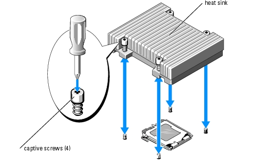
- Using a #2 Phillips screwdriver, loosen the four captive screws that secure the heat sink to the
system board. See Figure 5-9.
Figure 5-9. Installing and Removing the Heat Sink
- Wait 30 seconds for the heat sink to loosen from the processor.
- If the heat sink has not separated from the processor, carefully rotate the heat sink in a
clockwise, then counterclockwise, direction until it releases from the processor. Do not pry the
heat sink off of the processor.
- Lift the heat sink off of the processor and set the heat sink upside down so as not to
contaminate the thermal grease.
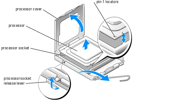
- Press down on the processor socket release lever, then pull the release lever upward to the fully
open position. See Figure 5-10.
- Open the processor cover. See Figure 5-10.
- Lift the processor vertically out of the socket. Leave the processor cover and release lever in
the open position so that the socket is ready for the new processor. See Figure 5-10.
Figure 5-10. Installing and Removing the Processor
- Unpack the new processor and heat sink.
- Ensure that the processor socket release lever is in the fully open position.
- Align the pin 1 corners of the processor and socket. See Figure 5-10.
|
|
NOTICE: You must position the processor correctly in the socket to avoid damaging the processor and the system board when you turn on the system. Be careful not to touch or bend the pins on the socket. |
- Set the processor lightly in the socket and ensure that the processor is level in the socket.
When the processor is positioned correctly, press it gently to seat it in the socket.
- Close the processor cover.
- Rotate the release lever back down until it snaps into place, securing the processor cover.
- Install the heat sink.
- Using a clean lint-free cloth, remove the existing thermal grease from the heat sink.
|
|
NOTE: Use the heat sink that you removed earlier in this procedure. |
- Apply thermal grease evenly to the top of the processor.
- Place the heat sink onto the processor. See Figure 5-9.
- Using a #2 Phillips screwdriver, tighten in a diagonal pattern the four captive screws that
secure the heat sink to the system board. See Figure 5-9.
- Install the cooling shroud. See "Installing the Cooling Shroud."
- Close the system. See "Closing the System" in "Troubleshooting Your System."
As the system boots, it detects the presence of the new processor and automatically changes the system configuration information in the System Setup program.
- Press <F2> to enter the System Setup program, and check that the processor information
matches the new system configuration.
See your User's Guide for instructions about using the System Setup program.
- Run the system diagnostics to verify that the new processor operates correctly.
See "Running the System Diagnostics" for information about running the diagnostics and troubleshooting processor problems.
Back to Contents Page