 Other Documents You May Need
Dell™ PowerVault™ 220S and 221S Systems User's Guide
Preventing Unauthorized Access to the System
Safety and Regulatory Information
Dell™ PowerVault™ 220S and 221S systems are reliable, flexible, external SCSI expansion enclosures designed to support multiple Dell storage environments and RAID configurations. Each system offers maximized drive-spindle count, hot-plug hard drives, optional redundant power, redundant cooling, rackmount capability, systems management features, and a modular design for easy upgrades. Most major components, including hard drives and power supply/cooling modules are hot-pluggable and can be removed and replaced easily. The enclosure management module (EMM), split-bus module, and SCSI terminator card are "warm-pluggable." This means they can be removed or inserted while the power is on, but all I/O activity has ceased.
This section describes the major hardware features of the system and identifies front- and back-panel components and LED indicators.
Besides this User's Guide, the following documentation is provided for your system:
 |
NOTE: Documentation updates which describe changes to your system are sometimes included with your system. Always read these updates before consulting any other documentation. |
You may also have one or more of the following documents:
Your system offers the following features:
Figure 1-1 shows the front-view orientation of both systems.
Figure 1-1. System Orientation
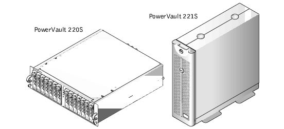
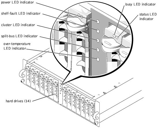
Figure 1-2 illustrates the LED indicators and components on the system's front panel. Table 1-1 lists the functions of the indicators on the front panel.
Figure 1-2. Front-Panel Features
|
LED Indicator |
Function |
|---|---|
Power (green) | At least one power supply is supplying power to the system. |
Shelf fault (amber) | One of the following conditions has occurred: power supply failure, EMM failure, cooling module failure, over-temperature condition, firmware currently being downloaded. |
Cluster (green) | Enclosure is configured for cluster mode. (For more information, see "Split-Bus Module.") |
Split bus (green) | Enclosure is configured for split bus mode. (For more information, see "Split-Bus Module.") |
Over temperature (amber) | An over-temperature condition has occurred. |
The primary EMM activates an audible alarm if any of the shelf fault conditions listed in Table 1-1 occur. If a critical event occurs, the alarm sounds continuously. If a noncritical event occurs, the alarm sounds every 10 seconds. Table 1-2 lists critical and noncritical events.
|
NOTE: The audible alarm is disabled by default. To enable the alarm, you must change the default setting using your array management software. For more information, see your array management software documentation. |
|
Critical Events |
Noncritical Events |
|---|---|
Two or more cooling-module blowers have failed or a cooling module is not installed. | One power supply has failed. |
One or more temperature sensors are in the critical range. | One cooling module blower has failed or is not installed. |
Split-bus module not installed. | One or more temperature sensors are in the warning range. |
| One EMM has failed. |
|
NOTE: It is rare for both EMMs to fail simultaneously. However, if this event occurs, the system cannot issue critical or noncritical event alarms for any system component. If both power supplies fail simultaneously, the system can issue critical or noncritical event alarms only if 5-V power is available. |
Each of your system's 14 hard-drive carriers have two LED indicators (see Figure 1-2 for locations). The first LED is a green busy indicator, controlled by the hard drive, that is illuminated when the hard drive is active on the SCSI bus. The second LED is a two-color (green and amber) status indicator. Table 1-3 lists the status indicator flash patterns.
|
Condition |
Status Indicator Pattern |
|---|---|
Slot empty, ready for insert/remove | Off |
Drive online, prepare for operation | Steady green |
Drive identify/special POD identify | Flashes green four times per second |
Prepare for removal | Flashes green twice per second at equal intervals |
Drive rebuild | Flashes green twice per second at unequal intervals |
Drive fail | Flashes amber four times per second |
Predicted failure | Flashes green, then amber, then off, repeating this sequence every two seconds |
Figure 1-3 illustrates the back-panel features for redundant systems. Figure 1-4 illustrates the back-panel features for nonredundant systems.
Figure 1-3. Back-Panel Features (Redundant Systems)
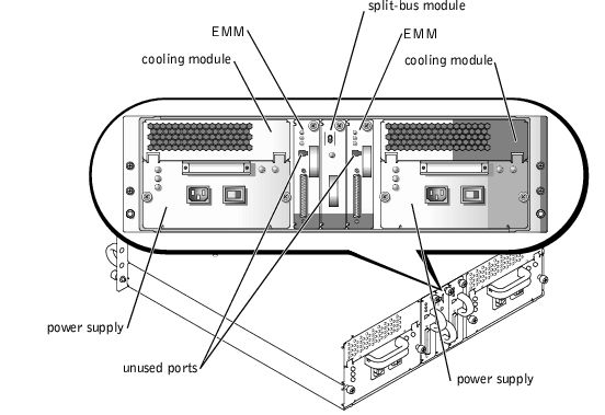
Figure 1-4. Back-Panel Features (Nonredundant Systems)

Figure 1-5 illustrates the back-panel module features and indicators.
Figure 1-5. Back-Panel Module Features and Indicators
Your system supports three SCSI bus modes controlled by the split-bus module:
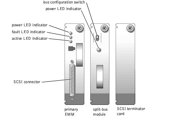
These modes are controlled by the position of the bus configuration switch when the system is turned on. Figure 1-6 illustrates the switch position for each mode.
Figure 1-6. Bus Configuration Switch Modes

The only difference between cluster mode and joined-bus mode is the SCSI ID occupied by the enclosure services processor. When cluster mode is detected, the processor SCSI ID changes from 6 to 15, allowing a second initiator to occupy SCSI ID 6. As a result, hard-drive slot 13 (normally occupying SCSI ID 15) is disabled, leaving 13 available hard-drive slots in cluster mode. For more information on SCSI ID assignments and cluster mode operation, see your Installation and Troubleshooting Guide. See Table 1-4 for a description of the split-bus module modes and functions.
|
NOTE: To change the SCSI bus mode, you must change the position of the bus configuration switch before turning on the system. Using the bus configuration switch while the system is on will not affect system operation. |
|
Mode |
Position of Bus Configuration Switch |
Function |
|---|---|---|
Joined-bus mode | Up | LVD termination on the split-bus module is disabled, electrically joining the two SCSI buses to form one contiguous bus. In this mode, neither the split-bus nor the cluster LED indicators on the front of the enclosure (see Figure 1-2 for locations) are illuminated. |
Split-bus mode | Center | LVD termination on the split-bus module is enabled and the two buses are electrically isolated, resulting in two seven-drive SCSI buses. The split-bus LED indicator on the front of the enclosure (see Figure 1-2 for location) is illuminated while the system is in split-bus mode. |
Cluster mode | Down | LVD termination is disabled and the buses are electrically joined. The cluster LED on the front of the enclosure is illuminated while the system is in cluster mode. |
The split-bus module has only one LED indicator (see Figure 1-5 for location), which is illuminated when the module is receiving power.
The EMM serves two primary functions in your storage system:
A system with redundant enclosure management features two EMMs that are designated as primary and secondary and that can be configured in either a cluster, joined-bus, or split-bus mode. A nonredundant configuration consists of one EMM and one SCSI terminator card, and can be configured in a joined-bus mode only. In a redundant system, only one EMM per SCSI bus is active at one time, so only one EMM per SCSI bus can respond to SCSI commands from an initiator.
In joined-bus and cluster modes, if a secondary EMM receives a message that the primary EMM has failed, the fault LED indicator on the primary EMM is illuminated and the condition is reported back to the host initiator. The secondary EMM will then become active and hold the failed primary in a state of reset until it is replaced. If the primary EMM detects that the secondary has failed, the secondary's fault LED indicator is illuminated and the failed status is reported back to the host initiator.
|
NOTE: In split-bus mode, each EMM controls half of the enclosure. If one EMM fails in split-bus mode, the second EMM will report the failure, but will not assume control of the entire SCSI bus. |
The primary EMM is always plugged into the slot on the left (viewed from the back of the system). In a redundant joined-bus configuration, the primary EMM assumes control of all enclosure functionality. In addition, the primary EMM is the only module that reports status of the system to the host initiator through SES and SAFTE protocols. Because the secondary EMM must assume the responsibilities of the primary in the event that the primary fails, both the primary and secondary EMMs are continuously monitoring the status of the system's components.
Table 1-5 lists the functions of each EMM LED indicator. See Figure 1-5 for the location of the indicator LEDs.
|
NOTE: If you have a nonredundant system with only one EMM installed, the only indicators that function are the power LED and active LED indicators. |
Your system supports two combined power supply and cooling modules. While the system is designed to operate normally with only one functional power supply, both cooling modules (with two blowers each) must be present for proper cooling. If only one power supply is needed, a blank must be inserted into the other slot to mount the second cooling module.
The power supply blank has the capacity to transfer power and control signals to and from the cooling module. In this nonredundant power-supply configuration, the cooling modules operate at higher speeds to maintain proper system cooling and produce a higher acoustical noise than in the redundant power-supply configuration.
If one blower within a cooling module fails, your system reverts to a nonredundant fan configuration. The remaining three blowers in the two cooling modules operate at higher speeds to maintain proper system cooling and produce higher acoustical noise than in the redundant fan configuration (with four blowers in two cooling modules).
 |
NOTICE: The system will operate for only five minutes with one cooling module installed. This allows you the necessary time to replace a failed cooling module. If both cooling modules are installed, the system will still operate if a single blower fails. While it is rare for more than one blower to fail simultaneously, if this event occurs, the system may shut down to prevent overheating. |
The cooling module is securely mounted to the power supply using a hook-and-latch fastener. This simplifies the removal and installation of cooling modules and power supplies.
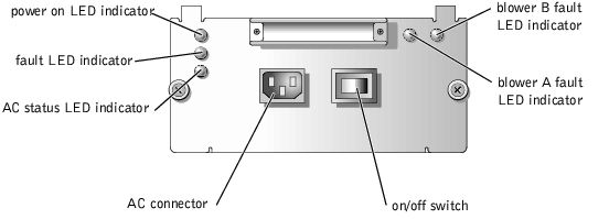
Table 1-6 lists the function of each power supply and cooling module LED indicator. See Figure 1-7 for the location of the indicators.
|
LED Indicator |
Function |
|---|---|
Power on (green) | Indicates DC output voltages are within specifications |
Fault (amber) | Indicates one of the DC output voltages is not within specifications |
AC status (green) | Indicates AC input voltage is within specifications regardless of the position of the power switch |
Blower A fault (amber) | Indicates failure of cooling module blower A |
Blower B fault (amber) | Indicates failure of cooling module blower B |
Figure 1-7. Power Supply and Cooling Module LED Features and Indicators
The PowerVault 220S can be secured with the lock on the rack door. The PowerVault 221S has a keylock mechanism on the top of the front bezel that prevents unauthorized access to the system.
A number of devices are available to protect against power problems such as power surges, transients, and power failures. The following subsections describe some of these devices.
Surge protectors are available in a variety of types and usually provide a level of protection commensurate with the cost of the device. Surge protectors prevent voltage spikes, such as those caused during an electrical storm, from entering a system through the electrical outlet. Surge protectors, however, do not offer protection against brownouts, which occur when the voltage drops more than 20 percent below the normal AC line voltage level.
Line conditioners go beyond the overvoltage protection of surge protectors. Line conditioners keep a system's AC power source voltage at a fairly constant level and, therefore, can handle brownouts. Because of this added protection, line conditioners cost more than surge protectors—up to several hundred dollars. However, these devices cannot protect against a complete loss of power.
Uninterruptible power supply (UPS) systems offer the most complete protection against variations in power because they use battery power to keep the system running when AC power is lost. The battery is charged by the AC power while it is available, so once AC power is lost, the battery can provide power to the system for a limited amount of time—from 15 minutes to an hour or so—depending on the UPS system.
UPS systems range in price from a few hundred dollars to several thousand dollars, with the more expensive units allowing you to run larger systems for a longer period of time when AC power is lost. UPS systems that provide only 5 minutes of battery power let you conduct an orderly shutdown of the system, but are not intended to provide continued operation. Surge protectors should be used with all UPS systems, and the UPS system should be Underwriters Laboratories (UL) safety-approved.
See your System Information document for important safety and regulatory information for your system.
Dell provides a number of tools to help with the installation, setup, and operation of your system. For more information on these tools, see "Getting Help" in your Installation and Troubleshooting Guide.