 Removing and Replacing the Fan Assembly
Dell™ PowerVault™ 715N Systems Installation and Troubleshooting Guide
Removing and Replacing the Fan Assembly
This section describes how to install the following options:
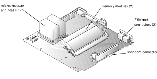
Use Figure 5-1 to locate the system board features.

|
CAUTION: Before you perform this procedure, you must turn off the system and disconnect it from its power source. For more information, see "Safety First—For You and Your System" in "Troubleshooting Your System." |
Figure 5-1. System Board Features
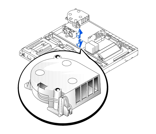
The fan assembly, which is located behind IDE hard drive 1, contains one fan.
Figure 5-2. Removing the Fan Assembly
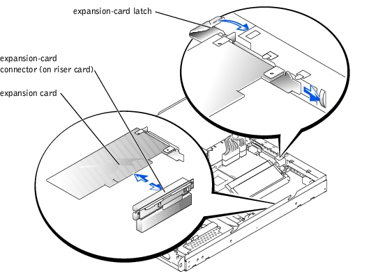
The system has capacity for one, low-profile PCI expansion card. You install the card by using a riser card (see Figure 5-3).
To install an expansion card, perform the following steps.
|
|
CAUTION: Before you perform this procedure, you must turn off the system and disconnect it from its power source. For more information, see "Safety First—For You and Your System" in "Troubleshooting Your System." |
|
|
CAUTION: See "Protecting Against Electrostatic Discharge" in the safety instructions in your System Information document. |
 |
NOTE: Keep this bracket in case you need to remove the expansion card. Installing a filler bracket over an empty expansion slot is necessary to maintain Federal Communications Commission (FCC) certification of the system. The brackets also keep dust and dirt out of the system and aid in proper cooling and airflow inside the system. |
Figure 5-3. Installing the Expansion Card
|
|
CAUTION: Before you perform this procedure, you must turn off the system and disconnect it from its power source. For more information, see "Safety First—For You and Your System" in "Troubleshooting Your System." |
See "Removing and Replacing the System Cover" in "Troubleshooting Your System."
|
NOTE: Installing a filler bracket over an empty expansion slot is necessary to maintain Federal Communications Commission (FCC) certification of the system. The brackets also keep dust and dirt out of the system and aid in proper cooling and airflow inside the system. |
The two memory module sockets on the system board can accommodate a minimum of 128 MB of registered SDRAM. The memory module sockets are located near the back edge of the system board (see Figure 5-1), behind hard drive 2.
You can upgrade the system by installing combinations of registered memory modules. If you receive an error message stating that maximum memory has been exceeded, see "Indicators, Messages, and Codes" for more information. You can purchase memory upgrade kits from Dell.
|
NOTE: The memory modules must be PC-133 compliant. |
|
NOTE: Parts of this procedure require you to use the console redirection function on the serial port. See your System Administrator's Guide for information about connecting to the system through console redirection. |
|
|
CAUTION: Before you perform this procedure, you must turn off the system and disconnect it from its power source. For more information, see "Safety First—For You and Your System" in "Troubleshooting Your System." |
|
|
CAUTION: See "Protecting Against Electrostatic Discharge" in the safety instructions in your System Information document. |
See "Removing and Replacing the System Cover" in "Troubleshooting Your System."
Figure 5-1 shows the location of the memory module sockets.
|
NOTE: If you use a version of Microsoft® Windows® 2000 earlier than Service Pack 2, the function keys do not work. You must press <Esc><2>. |
|
|
CAUTION: Before you perform this procedure, you must turn off the system and disconnect it from its power source. For more information, see "Safety First—For You and Your System" in "Troubleshooting Your System." |
|
|
CAUTION: See "Protecting Against Electrostatic Discharge" in the safety instructions in your System Information document. |
Figure 5-1 shows the location of the memory module sockets.
Figure 5-4. Installing and Removing a Memory Module
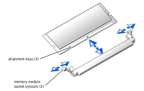
The memory module socket has two alignment keys that allow you to install the memory module in the socket in only one way.
When the memory module is properly seated in the socket, the ejectors on the memory module socket align with the ejectors on the other sockets with memory modules installed.
|
|
CAUTION: Before you perform this procedure, you must turn off the system and disconnect it from its power source. For more information, see "Safety First—For You and Your System" in "Troubleshooting Your System." |
|
|
CAUTION: See "Protecting Against Electrostatic Discharge" in the safety instructions in your System Information document. |
See "Removing and Replacing the System Cover" in "Troubleshooting Your System."
Figure 5-1 shows the location of the memory module sockets.
To take advantage of future options in speed and functionality, you can replace the processor.
Each processor and its associated Level 2 (L2) cache memory are contained in a pin grid array (PGA) package that is installed in a ZIF socket on the system board. The following subsection describes how to install or replace the microprocessor.
The following items are included in the microprocessor upgrade kit:
|
NOTE: Dell recommends that only a technically knowledgeable person should perform this procedure. |
See "Removing and Replacing the System Cover" in "Troubleshooting Your System."
|
|
CAUTION: See "Protecting Against Electrostatic Discharge" in the safety instructions in your System Information document. |
|
|
CAUTION: Never remove the heat sink from a microprocessor unless you intend to remove the microprocessor. The heat sink is necessary to maintain proper thermal conditions. |
|
|
CAUTION: The microprocessor and heat sink can become extremely hot. Be sure the microprocessor has had sufficient time to cool before handling. |
 |
NOTICE: Be careful not to bend any of the pins when removing the microprocessor. Bending the pins can permanently damage the microprocessor. |
If any of the pins on the microprocessor appear bent, see "Getting Help" for information about obtaining technical assistance from Dell.
|
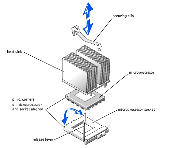
NOTE: Identifying the pin-1 corners is critical to positioning the microprocessor correctly. |
Identify the pin-1 corner of the microprocessor by locating the tiny gold triangle that extends from one corner of the large central rectangular area. The gold triangle points toward pin 1, which is also uniquely identified by a square pad.
|
NOTICE: Positioning the microprocessor incorrectly can permanently damage the microprocessor and the system when you turn on the system. When placing the microprocessor in the socket, be sure that all of the pins on the microprocessor enter the corresponding holes. Be careful not to bend the pins. |
If the release lever on the microprocessor socket is not positioned all the way up, move it to that position.
With the pin-1 corners of the microprocessor and socket aligned, set the microprocessor lightly in the socket and make sure all pins are matched with the correct holes in the socket. Because the system uses a ZIF micro-processor socket, do not use force, which could bend the pins if the microprocessor is misaligned. When the microprocessor is positioned correctly, it drops down into the socket with minimal pressure.
When the microprocessor is fully seated in the socket, rotate the socket release lever back down until it snaps into place, securing the microprocessor.
|
NOTE: If you use a version of Windows 2000 earlier than Service Pack 2, the function keys do not work. You must press <Esc><2>. |
See the system User's Guide for instructions.
See "Using the BIOS Setup Utility" in your User's Guide.
See "Running System Diagnostics" for information about running the diagnostics and troubleshooting any problems that might occur.
|
NOTE: Parts of this procedure require you to use the console redirection function on the serial port. See your System Administrator's Guide for information about connecting to the system through console redirection. |
The system battery maintains system configuration, date, and time information in a special section of memory when you turn off the system. The operating life of the battery ranges from 2 to 5 years, depending on how you use the system (for example, if you keep the system turned on most of the time, the battery gets little use and, thus, lasts longer).
You might need to replace the battery if an incorrect time or date displays during the boot routine along with a message about wrong time, invalid configuration information, or bad CMOS checksum.
To determine if you need to replace the battery:
If the date and time are not correct in the BIOS Setup utility, replace the battery.
|
NOTE: Some software might cause the system time to speed up or slow down. If the system seems to operate normally except for the time kept in the BIOS Setup utility, the problem might be caused by software rather than by a defective battery. |
|
NOTE: If the system is turned off for long periods of time (for weeks or months), the SDRAM might lose its system configuration information. This situation is not caused by a defective battery. |
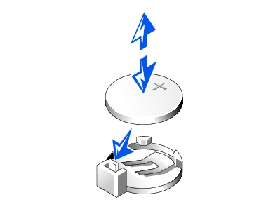
You can operate the system without a battery; however, the system configuration information maintained by the battery in SDRAM is erased each time you shut down the system. Therefore, you must re-enter the system configuration information and reset the options each time the system boots until you replace the battery. The battery is a 3.0-volt (V) battery.
To remove the battery, perform the following steps.
|
|
CAUTION: Before you perform this procedure, you must turn off the system and disconnect it from its power source. For more information, see "Safety First—For You and Your System" in "Troubleshooting Your System." |
|
|
CAUTION: There is a danger of a new battery exploding if it is incorrectly installed. Replace the battery only with the same or equivalent type recommended by the manufacturer. Discard used batteries according to the manufacturer's instructions. |
See "Using the BIOS Setup Utility," in the User's Guide for instructions.
|
|
CAUTION: See "Protecting Against Electrostatic Discharge" in the safety instructions in your System Information document. |
Figure 5-6. Installing the Battery
Also, re-enter any system configuration information that is no longer displayed on the BIOS Setup screens, and then exit the BIOS Setup utility.