Dell™ PowerEdge™ 700 Systems Installation and Troubleshooting Guide
The system, applications, and operating systems can identify problems and alert you to them. Any of the following can indicate when the system is not operating properly:
This section describes each type of message, lists the possible causes, and provides steps to resolve any problems indicated by a message. The system indicators and features are illustrated in this section.
Figure 2-1 shows the front-panel features of the system. Table 2-1 describes the front-panel features.
Figure 2-1. Front Panel Features
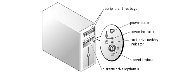
Table 2-1. Front-Panel Features and Indicators
Figure 2-2 shows the back-panel features of the system. Table 2-2 describes the back-panel features.
Figure 2-2. Back-Panel Features
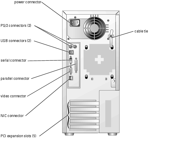
Table 2-2. Back-Panel Features
|
Component |
Description |
|---|---|
Provide information on NIC status. See "NIC Indicator Codes." | |
Provide two 32-bit/33-MHz, 5-V PCI slots and three 64-bit/33-MHz, 3.3-V PCI-X slots | |
The NIC connector on the back panel has indicators that provide information on network activity and link status (see Figure 2-3). Table 2-3 lists the NIC indicator codes.

Table 2-3. NIC Indicator Codes
Each SCSI hard-drive carrier has two indicators: a busy indicator and a status indicator (see Figure 2-4). The indicators provide information on the status of the respective hard drive.
Figure 2-4. Hard-Drive Indicators
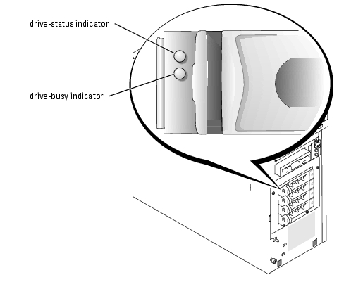
Table 2-4 lists the drive-status indicator codes. Different codes display as drive events occur in the system. For example, in the event of a hard-drive failure, the "drive fail" code appears. After the drive is selected for removal, the "preparing for removal" code appears. After the replacement drive is installed, the "preparing for operation, drive online" code appears.
The drive-busy indicator signifies whether the hard drive is active on the SCSI bus. This indicator is controlled by the hard drive.
Table 2-4. SCSI Hard-Drive Status Indicator Codes
|
Drive-Status Indicator |
Indicator Code |
|---|---|
Drive being identified, prepared for removal, or drive offline | |
System messages appear on the screen to notify you of a possible problem with the system. Table 2-5 lists the system messages that can occur and the probable cause and corrective action for each message.
 |
NOTE: If you receive a system message that is not listed in Table 2-5, check the documentation for the application that is running when the message appears or the operating system's documentation for an explanation of the message and recommended action. |
|
Message |
Causes |
Corrective Actions |
|---|---|---|
Address mark not found | Faulty CD/diskette-drive subsystem or hard-drive subsystem; faulty system board. | See "Troubleshooting a Diskette Drive," "Troubleshooting a CD, DVD, or CD-RW/DVD Drive," "Troubleshooting SCSI Hard Drives," or "Troubleshooting SATA Hard Drives" in "Troubleshooting Your System." |
Alert! Back system fan was not detected. | See "Troubleshooting System Cooling Problems" in "Troubleshooting Your System." | |
Alert! Front system fan was not detected. | ||
Alert! Cover was previously removed. | ||
Alert! DIMM(s) n are unsupported | BIOS detected DIMM SPD contains invalid value or SPD checksum failed. | Replace the defective memory module. See "Memory Modules" in "Installing System Options." |
Alert! Invalid configuration! When using a single hard disk drive, SATA Port 0 must be used. | SATA hard drive not connected to correct connector on system board. | If the system is configured with one hard drive, ensure that the drive's interface cable is connected to the SATA PORT0 connector on the system board. See Figure A-3 for connector location. |
Alert! Mismatched DIMMs are detected in bank(s): Bank n | Memory modules installed in the specified bank are not the same type and size; faulty memory module(s). | Ensure that all banks contain memory modules of the same type and size and that they are properly installed. If the problem persists, see "Troubleshooting System Memory" in "Troubleshooting Your System." |
Alert! Previous back system fan failure. | ||
Alert! Previous front system fan failure. | ||
Alert! Previous thermal event. | BIOS detected a thermal event before the last system startup. | Ensure that thermal grease is applied to the heat sink and the heat sink is installed properly. Ensure that the front and back system fans are functioning properly. See "Replacing the Processor" in "Installing System Options" and "Troubleshooting System Cooling Problems" in "Troubleshooting Your System." |
Alert! Previous voltage failure. | ESM detected sensor voltage out of range before last system startup. | |
Amount of available memory limited to 256 MB! | Disable OS Install Mode in the System Setup program (see "Using the System Setup Program" in your User's Guide). | |
Auxiliary device failure | Loose or improperly connected mouse or keyboard cable; faulty mouse or keyboard. | See "Troubleshooting the Mouse" and "Troubleshooting the Keyboard" in "Troubleshooting Your System." |
BIOS Update Attempt Failed! | Retry the BIOS firmware update (see "Getting Help"). | |
Caution! NVRAM_CLR jumper is installed on system board. Please run setup. | Remove the NVRAM_CLR jumper (see Figure A-2 for jumper location). Check the System Setup configuration settings (see "Using the System Setup Program" in your User's Guide). | |
Data error | Faulty diskette, diskette drive, CD drive, tape drive, or hard drive. | Replace the diskette. If the problem persists, see "Troubleshooting a Diskette Drive," "Troubleshooting a CD, DVD, or CD-RW/DVD Drive," "Troubleshooting SATA Hard Drives," or "Troubleshooting SCSI Hard Drives" in "Troubleshooting Your System." |
Decreasing available memory | See "Troubleshooting System Memory" in "Troubleshooting Your System." | |
Diskette drive n seek failure | Incorrect configuration settings in the System Setup program. | Run the System Setup program to correct the settings (see "Using the System Setup Program" in your User's Guide). |
See "Troubleshooting a Diskette Drive" in "Troubleshooting Your System." | ||
Diskette read failure | ||
Diskette subsystem reset failed | See "Troubleshooting a Diskette Drive" in "Troubleshooting Your System." | |
Diskette write protected | Move the write-protect tab on the diskette to the disabled position. | |
Drive not ready | ||
Embedded server management error | Faulty or improperly installed remote access controller (RAC) or loose cable connection. | Ensure that the RAC's cable is properly connected. Ensure that the RAC is properly installed. See "Expansion Cards" in "Installing System Options." If the problem persists, see "Getting Help." |
Error: More than one RAC detected, system halted. | Two RACs are installed, or faulty or improperly installed RAC. | Ensure that there is only one RAC installed and that it is installed in the correct slot. Ensure that the RAC is properly installed. See "Expansion Cards" in "Installing System Options." If the problem persists, see "Getting Help." |
Error: RAC cannot be used with an add-in video card in this slot. | Ensure that the RAC is installed in the correct slot. See "Expansion Cards" in "Installing System Options." | |
Error: RAC is not in the correct PCI slot, system halted. | Ensure that the RAC is installed in the correct PCI slot. See "Troubleshooting Expansion Cards" in "Troubleshooting Your System." | |
Error: Remote Access Card initialization failure. | Ensure that the RAC is properly installed. See "Troubleshooting Expansion Cards" in "Troubleshooting Your System." | |
Gate A20 failure | See "Getting Help." | |
General failure | ||
Hard disk controller failure | Incorrect configuration settings in System Setup program; improperly installed hard drive; loose interface or power cable; faulty hard-drive controller subsystem. | Run the System Setup program to correct the drive type setting (see "Using the System Setup Program" in your User's Guide). If the problem persists, see "Troubleshooting SCSI Hard Drives" or "Troubleshooting SATA Hard Drives" in "Troubleshooting Your System." |
Invalid memory configuration detected. Potential corruption exists! | Memory module installation guidelines have not been properly followed. | See "Memory Module Installation Guidelines" in "Installing System Options." |
Keyboard controller failure | See "Getting Help." | |
Keyboard data line failure | Loose or improperly connected keyboard cable; faulty keyboard; faulty keyboard controller. | See "Troubleshooting the Keyboard" in "Troubleshooting Your System." |
Keyboard failure | ||
Keyboard stuck key failure | ||
Memory address line failure at address, read value expecting value | See "Troubleshooting System Memory" in "Troubleshooting Your System." | |
Memory double word logic failure at address, read value expecting value | ||
Memory odd/even logic failure at start address to end address | ||
Memory write/read failure at address, read value expecting value | ||
Memory allocation error | ||
Memory bank population error! | Memory module installation guidelines have not been properly followed. | See "Memory Module Installation Guidelines" in "Installing System Options." |
Memory parity interrupt at address | See "Troubleshooting System Memory" in "Troubleshooting Your System." | |
Memory tests terminated by keystroke | The spacebar was pressed during POST to terminate the memory test. | |
No boot device available | Faulty or missing CD/diskette-drive subsystem, hard drive, or hard-drive subsystem. | Use a bootable diskette, CD, or hard drive. If the problem persists, see "Troubleshooting a Diskette Drive," "Troubleshooting a CD, DVD, or CD-RW/DVD Drive," "Troubleshooting SATA Hard Drives," or "Troubleshooting SCSI Hard Drives" in "Troubleshooting Your System." |
No boot sector on hard- disk drive | Check the hard-drive configuration settings in the System Setup program (see "Using the System Setup Program" in your User's Guide). | |
No timer tick interrupt | See "Getting Help." | |
Non-system disk or disk error | Faulty diskette, CD/diskette-drive subsystem, or hard-drive subsystem. | See "Troubleshooting a Diskette Drive," "Troubleshooting a CD, DVD, or CD-RW/DVD Drive," "Troubleshooting SATA Hard Drives," or "Troubleshooting SCSI Hard Drives" in "Troubleshooting Your System." If the problem persists, see "Getting Help." |
Not a boot diskette | ||
PCI BIOS failed to install | Loose cable(s) to expansion card(s); faulty or improperly installed expansion card. | Ensure that all appropriate cable(s) are securely connected to the expansion card(s). If the problem persists, see "Troubleshooting Expansion Cards" in "Troubleshooting Your System." |
Plug & Play Configuration error | Install the NVRAM_CLR jumper and reboot the system (see Figure A-2 for jumper location). If the problem persists, see "Troubleshooting Expansion Cards" in "Troubleshooting Your System." | |
Primary drive n configuration error Primary drive n failure | Ensure that the CD drive cables are properly connected. See "Troubleshooting a CD, DVD, or CD-RW/DVD Drive" in "Troubleshooting Your System." | |
Primary drive n not found | The specified drive on the primary channel of the integrated hard drive controller is set to Auto in the System Setup program, but no drive is attached; improperly installed hard drive; loose interface or power cable. | Run the System Setup program to correct the drive settings (see "Using the System Setup Program" in your User's Guide). If the problem persists, see "Troubleshooting SATA Hard Drives" or "Troubleshooting SCSI Hard Drives" in "Troubleshooting Your System." |
Read fault | Faulty diskette, CD/diskette-drive subsystem, or hard-drive subsystem. | See "Troubleshooting a Diskette Drive," "Troubleshooting a CD, DVD, or CD-RW/DVD Drive," "Troubleshooting SATA Hard Drives," or "Troubleshooting SCSI Hard Drives" in "Troubleshooting Your System." If the problem persists, see "Getting Help." |
Requested sector not found | ||
Reset failed | Improperly connected diskette drive, tape drive, hard drive, or power cable. | Ensure that all cables are securely connected. If the problem persists, see "Getting Help." |
ROM bad checksum = address | See "Troubleshooting Expansion Cards" in "Troubleshooting Your System." | |
SATA port n hard disk drive auto-sensing error SATA port n hard disk drive configuration error SATA port n hard drive failure | Ensure that the hard drive cables are properly connected. See "Troubleshooting a SATA Hard Drive Connected to the Integrated Drive Controller" and "Troubleshooting a SATA Hard Drive in a RAID Configuration (When Available)" in "Troubleshooting Your System." | |
SATA port n hard drive not found | Incorrect configuration settings in the System Setup program. The drive setting is Auto but no drive is installed. | Run the System Setup program to correct the settings. See "Using the System Setup Program" in your User's Guide. |
Sector not found | Replace the diskette. If the problem persists, replace the hard drive. See "Hard Drives" in "Installing Drives." | |
Seek error | ||
Seek operation failed | ||
Shutdown failure | See "Troubleshooting System Memory" in "Troubleshooting Your System." | |
Time-of-day clock stopped | See "Troubleshooting the System Battery" in "Troubleshooting Your System." | |
Time-of-day not set - please run SETUP program | Check the Time and Date settings (see "Using the System Setup Program" in your User's Guide). If the problem persists, replace the system battery (see "System Battery" in "Installing System Options"). | |
Timer chip counter 2 failed | See "Getting Help." | |
Unexpected interrupt in protected mode | Faulty or improperly installed memory modules or faulty system board. | See "Troubleshooting System Memory" in "Troubleshooting Your System." If the problem persists, see "Getting Help." |
Unsupported CPU stepping detected | Update the BIOS firmware (see "Getting Help"). | |
Utility partition not available | The <F10> key was pressed during POST, but no utility partition exists on the boot hard drive. | Create a utility partition on the boot hard drive (see the Dell OpenManage Server Assistant CD). |
Warning! No microcode update loaded for processor n | Update the BIOS firmware (see "Getting Help"). | |
Write fault | Faulty diskette, CD/diskette-drive subsystem, hard drive, or hard-drive subsystem. | See "Troubleshooting a Diskette Drive," "Troubleshooting a CD, DVD, or CD-RW/DVD Drive," Troubleshooting SATA Hard Drives," or "Troubleshooting SCSI Hard Drives" in "Troubleshooting Your System." |
Write fault on selected drive |
If an error that cannot be reported on the screen occurs during POST, the system may emit a series of beeps that identifies the problem.
|
NOTE: If the system boots without a keyboard, mouse, or monitor attached, the system does not issue beep codes related to those peripherals. |
If a beep code is emitted, write down the series of beeps and then look it up in Table 2-6. If you are unable to resolve the problem by looking up the meaning of the beep code, use system diagnostics to identify the possible cause. If you are still unable to resolve the problem, see "Getting Help."
|
Code |
Cause |
Corrective Action |
|---|---|---|
See "Troubleshooting the Processor" in "Troubleshooting Your System." | ||
See "Getting Help." | ||
Reflash the BIOS firmware (see "Getting Help"). | ||
See "Troubleshooting System Memory" in "Troubleshooting Your System." | ||
See "Getting Help." | ||
See "Troubleshooting the Keyboard" in "Troubleshooting Your System." | ||
See "Getting Help." | ||
See "Troubleshooting Expansion Cards" in "Troubleshooting Your System." | ||
See "Troubleshooting System Memory" in "Troubleshooting Your System." | ||
Install memory modules of the same type and size in bank n (see "Memory Modules" in "Installing System Options"). | ||
See "Getting Help." | ||
See "Troubleshooting the System Battery" in "Troubleshooting Your System." | ||
See "Getting Help." | ||
See "Troubleshooting the Processor" in "Troubleshooting Your System." |
A warning message alerts you to a possible problem and prompts you to respond before the system continues a task. For example, before you format a diskette, a message will warn you that you may lose all data on the diskette. Warning messages usually interrupt the task and require you to respond by typing y (yes) or n (no).
|
NOTE: Warning messages are generated by either the application or the operating system. For more information, see "Finding Software Solutions" and the documentation that accompanied the operating system or application. |
When you run system diagnostics, an error message may result. Diagnostic error messages are not covered in this section. Record the message on a copy of the Diagnostics Checklist in "Getting Help," and then follow the instructions in that section for obtaining technical assistance.
Systems management software generates alert messages for your system. Alert messages include information, status, warning, and failure messages for drive, temperature, fan, and power conditions. For more information, see the systems management software documentation.
