Back to Contents Page
Installing Drives
Dell™ PowerEdge™ SC1420 Systems Installation and Troubleshooting Guide
 General Installation Guidelines
Front-Panel Inserts
Hard Drives
Installing a SATA or SCSI Controller Card
Diskette Drive (Optional)
5.25-Inch Optical and Tape Drives
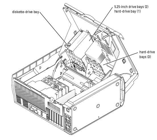
The drive bays in your system provide space for up to four SATA or SCSI hard drives, two 5.25-inch optical drives, and an optional diskette drive. See Figure 7-1.
Figure 7-1. Drive Locations Inside the System
General Installation Guidelines
IDE Drive Installation Guidelines
When you connect two IDE devices to a single IDE interface cable and configure them for the Cable Select setting, the device attached to the last connector on the interface cable is the primary (master) or boot device (drive 0), and the device attached to the middle connector on the interface cable is the secondary (slave) device (drive 1). See the drive documentation in your upgrade kit for information on configuring drives for the Cable Select setting.
Because Cable Select is the default setting, you do not need to set any additional drives as a primary or secondary drive.
SCSI Installation Guidelines
Although SCSI drives are installed in essentially the same way as other drives, their configuration requirements are different. To install and configure a SCSI drive, follow the guidelines in the following subsections.
 |
NOTE: SCSI devices installed by Dell are configured correctly during the manufacturing process. You do
not need to set the SCSI ID for these drives.
|
SCSI Interface Cables
SCSI interface connectors are keyed for correct insertion. Keying ensures that the pin-1 wire in the cable connects to pin 1 in the connectors on both ends. When you disconnect an interface cable, take care to grasp the cable connector, rather than the cable itself, to avoid stress on the cable.
SCSI ID Numbers
Each drive attached to a SCSI controller must have a unique SCSI ID number from 0 to 15.
- The SCSI hard drive from which the system boots is configured as SCSI ID 0.
- If you install an additional SCSI drive or change your SCSI configuration, see the documentation for each SCSI drive for information on setting the appropriate SCSI ID number.
|
NOTE: There is no requirement that SCSI ID numbers be assigned sequentially or that drives be
attached to the interface cable in order by ID number.
|
SCSI Device Termination
SCSI logic requires that termination be enabled for the two drives at opposite ends of the SCSI chain and disabled for all drives in between. For internal SCSI drives, termination is configured automatically. See the documentation provided with any optional SCSI drive you purchase for information on disabling termination.
Configuring the Boot Drive
The drive or device from which the system boots is determined by the boot order specified in the System Setup program. See "Using the System Setup Program" in your User's Guide. To boot the system from a hard drive or drive array, the drive(s) must be connected to the appropriate controller:
- To boot from a SCSI hard drive, the drive must be connected to the optional SCSI controller card. See the documentation that accompanied the controller card.
After you open and close the cover, the chassis intrusion detector, if enabled, causes the following message to appear on the screen at the next computer start-up:
ALERT! Cover was previously removed.
- Reset the chassis intrusion detector by changing Chassis Intrusion to Enabled or Enabled-Silent.
Front-Panel Inserts
If you are installing a new 5.25-inch drive, remove the front-panel inserts to allow external access to the drive. To gain access to the front-panel insert, you might need to remove a device.

|
CAUTION: Only trained service technicians are authorized to open the system cover and access any of the components inside the system. See your System Information Guide for complete information about safety precautions, working inside the computer, and protecting against electrostatic discharge. |
- Turn off the system and attached peripherals, and disconnect the system from the electrical
outlet.
- Open the system. See "Opening the System" in "Troubleshooting Your System."
- If applicable, remove a device. See the appropriate removal procedure.
- Squeeze the insert tabs until the insert pops free of the front-panel cover. See Figure 7-2.
Figure 7-2. Removing Front-Panel Inserts

Hard Drives
Your system contains up to four SATA or SCSI non-hot-plug hard drives. The integrated SATA controller supports two SATA hard drives. If more than two SATA drives are installed, they must be connected to an optional SATA controller card. If your system contains SCSI hard drives, they must be connected to an optional SCSI controller card.
The fourth hard drive is installed in the 5.25-inch drive bay (see Figure 7-1) using an adapter. After installing the drive and adapter, the removing and installing procedures are the same as the other hard drives.
The basic steps for removing and installing SATA and SCSI hard drives are the same.
Removing a Hard Drive
|
|
CAUTION: Only trained service technicians are authorized to open the system and access any of the components inside the system. See your System Information Guide for complete information about safety precautions, working inside the computer, and protecting against electrostatic discharge. |
- Turn off the system and attached peripherals, and disconnect the system from the electrical
outlet.
- Open the system. See "Opening the System" in "Troubleshooting Your System."
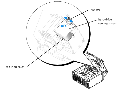
- On the hard-drive cooling shroud, squeeze the two tabs that secure the shroud to the cover
and rotate the shroud away from the cover. See Figure 7-4.
- Remove the hard-drive cooling shroud from the system.
Figure 7-3. Removing or Installing the Hard-Drive Cooling Shroud
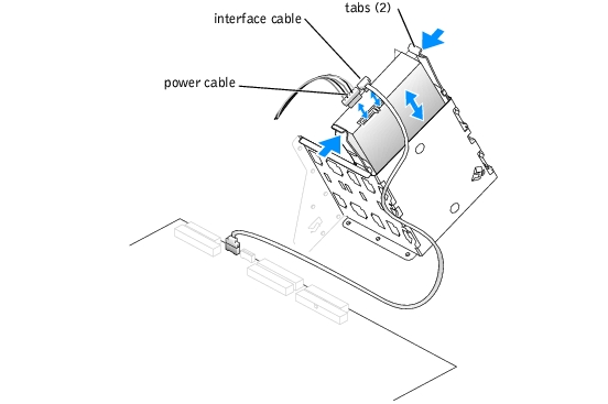
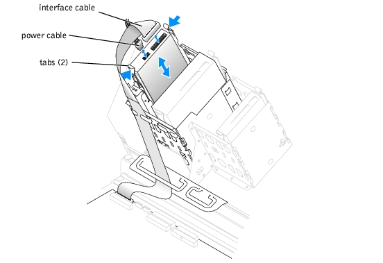
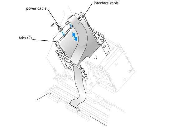
- Disconnect the power and interface cables from the hard drive. See Figure 7-4 and Figure 7-5.
- Press in on the tabs on each side of the drive and slide the drive up and out of the drive bay.
 |
NOTICE: When replacing the hard-drive cooling shroud, ensure that the cables are properly routed to
prevent damaging the cables.
|
- Insert the tabs of the hard-drive cooling shroud into the securing holes in the hard-drive bay.
See Figure 7-3.
- While rotating the shroud up, squeeze the two tabs and secure the shroud to the cover.
- Close the system. See "Closing the System" in "Troubleshooting Your System."
- Reconnect the system to the electrical outlet, and turn on the system and attached
peripherals.
Figure 7-4. Removing or Installing a SCSI Hard Drive

Figure 7-5. Removing or Installing a SATA Hard Drive
Installing a Hard Drive
|
|
CAUTION: Only trained service technicians are authorized to open the system and access any of the components inside the system. See your System Information Guide for complete information about safety precautions, working inside the computer, and protecting against electrostatic discharge. |
- Turn off the system and attached peripherals, and disconnect the system from the electrical
outlet.
- Open the system. See "Opening the System" in "Troubleshooting Your System."
- Unpack the hard drive, and prepare it for installation.
- Check the documentation for the drive to verify that it is configured for your system.
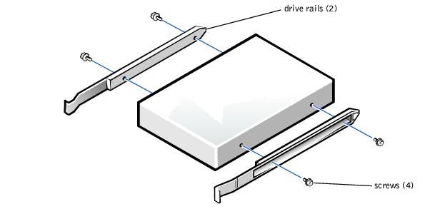
- If the hard drive does not have the drive rails attached, attach the drive rails to the new drive
by aligning the screw holes on the drive with the screw holes on the drive rails and then
inserting and tightening all four screws (two screws on each rail). See Figure 7-6.
If you are installing a fourth hard drive in the 5.25-inch drive bay, proceed to step 6.
If you are installing a drive in the hard-drive bay, proceed to step 10.
Figure 7-6. Installing Drive Rails
- Attach the adapter rails to the adapter by aligning the screw holes on the adapter with the
screw holes on the rails and then inserting and tightening all four screws (two on each rail).
See Figure 7-7.
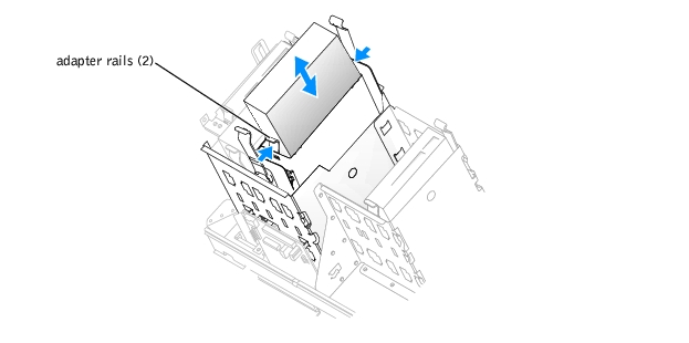
- Slide the adapter into the 5.25-inch drive bay until the tabs on the rails securely click into
position. See Figure 7-8.
Figure 7-7. Installing the Adapter Rails
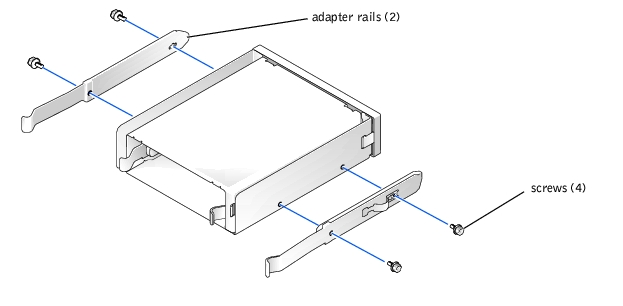
Figure 7-8. Installing the Adapter
- On the hard-drive cooling shroud, squeeze the two tabs that secure the shroud to the cover
and rotate the shroud away from the cover. See Figure 7-3.
- Remove the hard-drive cooling shroud from the system.
- Slide the new drive into the drive bay or the adapter until the tabs on the rails securely click
into position.
- Connect the power cable to the drive. See Figure 7-4 and Figure 7-5.
- Connect the interface cable to the drive:
- Connect SATA hard drives to the SATA0 and SATA1 connectors on the system board or to the SATA controller card if more than two SATA hard drives are installed. See the documentation for the controller card.
- Connect SCSI hard drives to the SCSI controller card. See the documentation for the controller card.
See Figure A-3 for the location of the drive interface connectors on the system board.
|
NOTICE: When replacing the hard-drive cooling shroud, ensure that the cables are properly routed to
prevent damaging the cables.
|
- Insert the tabs of the hard-drive cooling shroud into the securing holes in the hard-drive bay.
See Figure 7-3.
- While rotating the shroud up, squeeze the two tabs and secure the shroud to the cover.
- Close the system. See "Closing the System" in "Troubleshooting Your System."
- Reconnect the system to the electrical outlet, and turn on the system and attached
peripherals.
- Enter the System Setup program and ensure that the drive's controller is enabled. See "Using
the System Setup Program" in the User's Guide.
- Partition and logically format your drive before you go to the next step.
See the documentation for your operating system for instructions.
- Test the hard drive by running the system diagnostics. See "Running System Diagnostics."
- If the drive you just installed is the primary drive, install your operating system on the hard
drive.
Installing a SATA or SCSI Controller Card
See "Installing an Expansion Card" in "Installing System Components" for instructions about installing the card and routing the cables.
Diskette Drive (Optional)
The system supports an optional standard diskette drive.
Removing the Diskette Drive
|
|
CAUTION: Only trained service technicians are authorized to open the system cover and access any of the components inside the system. See your System Information Guide for complete information about safety precautions, working inside the computer, and protecting against electrostatic discharge. |
- Turn off the system and attached peripherals, and disconnect the system from the electrical
outlet.
- Open the system. See "Opening the System" in "Troubleshooting Your System."
- Disconnect the power and interface cables from the diskette drive. See Figure 7-9.
- Press in on the tabs on each side of the drive and slide the drive up and out of the drive bay.
- Close the system. See "Closing the System" in "Troubleshooting Your System."
- Reconnect the system to the electrical outlet, and turn on the system and attached
peripherals.
Installing an Optional Diskette Drive
|
|
CAUTION: Only trained service technicians are authorized to open the system cover and access any of the components inside the system. See your System Information Guide for complete information about safety precautions, working inside the computer, and protecting against electrostatic discharge. |
- Turn off the system and attached peripherals, and disconnect the system from the electrical
outlet.
- Open the system. See "Opening the System" in "Troubleshooting Your System."
- Unpack the replacement diskette drive, and prepare it for installation.
- Check the documentation for the drive to verify that it is configured for your system.
- If your new diskette drive does not have the drive rails attached, attach the drive rails to the
new drive by aligning the screw holes on the drive with the screw holes on the drive rails and
then inserting and tightening all four screws (two screws on each rail). See Figure 7-6.
- Slide the drive into the diskette-drive bay until the tabs on the rails securely click into
position.
- Connect the power cable to the drive. See Figure 7-9.
Figure 7-9. Removing or Installing an Optional Diskette Drive
- Connect the interface cable to the drive. See Figure 7-9.
See Figure A-3 for the location of the diskette-drive interface connector on the system board.
- Close the system. See "Closing the System" in "Troubleshooting Your System."
- Reconnect the system to the electrical outlet, and turn on the system and attached
peripherals.
- Enter the System Setup program and ensure that the drive's controller is enabled. See "Using
the System Setup Program" in the User's Guide.
- Test the drive by running the system diagnostics. See "Running System Diagnostics."
5.25-Inch Optical and Tape Drives
You can install an additional 5.25-inch drive of your choice in the second 5.25-inch drive bay. See Figure 7-1. If you are installing a tape backup unit (TBU), it must be installed in the second bay.
Installing a 5.25-Inch Drive
|
|
CAUTION: Only trained service technicians are authorized to open the system cover and access any of the components inside the system. See your System Information Guide for complete information about safety precautions, working inside the computer, and protecting against electrostatic discharge. |
- Unpack the drive and prepare the drive for installation.
For instructions, see the documentation that accompanied the drive. Also, see "IDE Drive Installation Guidelines" for information on configuring the drive.
- If the drive does not have the drive rails attached, attach the drive rails to the new drive by
aligning the screw holes on the drive with the screw holes on the drive rails and then inserting
and tightening all four screws (two screws on each rail). See Figure 7-6.
- Turn off the system, including any attached peripherals, and disconnect the system from the
electrical outlet.
- Open the system. See "Opening the System" in "Troubleshooting Your System."
- Remove the front-panel insert for the empty drive bay. See "Front-Panel Inserts."
- Slide the drive into the drive bay until the tabs on the rails securely click into position.
- Connect the power cable to the drive. See Figure 7-10.
Figure 7-10. Installing a 5.25-Inch Drive
- Connect the interface cable from the drive to the IDE2 connector on the system board. See
Figure 7-10 and Figure A-3.
- Close the system. See "Closing the System" in "Troubleshooting Your System."
- Reconnect the system to the electrical outlet, and turn on the system and attached
peripherals.
- Enter the System Setup program and ensure that the drive's IDE controller is enabled. See
"Using the System Setup Program" in the User's Guide.
- Test the drive by running the system diagnostics. See "Running System Diagnostics."
Back to Contents Page