General Installation Guidelines
Dell™ PowerEdge™ 400SC Systems Installation and Troubleshooting Guide
General Installation Guidelines
Installing a SCSI Controller Card
5.25-Inch Optical and Tape Drives
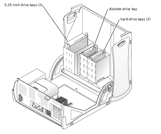
The drive bays in your system provide space for up to two IDE, SATA (when available), or SCSI hard drives, two 5.25-inch drives, and a diskette drive. See Figure 7-1.
Figure 7-1. Drive Locations Inside the System
When you connect two IDE devices to a single IDE interface cable and configure them for the Cable Select setting, the device attached to the last connector on the interface cable is the primary (master) or boot device (drive 0), and the device attached to the middle connector on the interface cable is the secondary (slave) device (drive 1). See the drive documentation in your upgrade kit for information on configuring drives for the Cable Select setting.
Because Cable Select is the default setting, you do not need to set any additional drives as a primary or secondary drive.
Although SCSI drives are installed in essentially the same way as other drives, their configuration requirements are different. To install and configure a SCSI drive, follow the guidelines in the following subsections.
 |
NOTE: SCSI devices installed by Dell are configured correctly during the manufacturing process. You do not need to set the SCSI ID for these drives. |
SCSI interface connectors are keyed for correct insertion. Keying ensures that the pin-1 wire in the cable connects to pin 1 in the connectors on both ends. When you disconnect an interface cable, take care to grasp the cable connector, rather than the cable itself, to avoid stress on the cable.
Each drive attached to a SCSI controller must have a unique SCSI ID number from 0 to 15.
|
NOTE: There is no requirement that SCSI ID numbers be assigned sequentially or that drives be attached to the interface cable in order by ID number. |
SCSI logic requires that termination be enabled for the two drives at opposite ends of the SCSI chain and disabled for all drives in between. For internal SCSI drives, termination is configured automatically. See the documentation provided with any optional SCSI drive you purchase for information on disabling termination.
After you install a SCSI hard drive, Primary Drive 0 and Primary Drive 1 should be set to None in the System Setup program if no IDE hard drives are installed. If you have any IDE devices on the second IDE channel, such as a CD or tape drive, Secondary Drive 0 and/or Secondary Drive 1 should be set to Auto.
The drive or device from which the system boots is determined by the boot order specified in the System Setup program. See "Using the System Setup Program" in your User's Guide. To boot the system from a hard drive or drive array, the drive(s) must be connected to the appropriate controller:
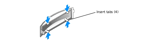
If you are installing a new TBU drive, optical drive, or other 5.25-inch drive, remove the front-panel inserts to allow external access to the drive. To gain access to the front-panel insert, you might need to remove a device.
Figure 7-2. Removing Front-Panel Inserts
Your system contains up to two IDE, SATA (when available), or SCSI non-hot-plug hard drives. If your system contains SCSI hard drives, they must be connected to an optional SCSI controller card.
The basic steps for removing and installing IDE, SATA, and SCSI hard drives are the same.

|
CAUTION: See your System Information Guide for complete information about safety precautions, working inside the computer, and protecting against electrostatic discharge. |
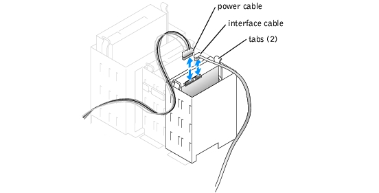
Figure 7-3. Removing or Installing an IDE or SCSI Hard Drive
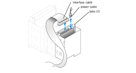
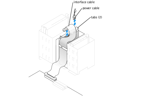
Figure 7-4. Removing or Installing a SATA Hard Drive
|
|
CAUTION: See your System Information Guide for complete information about safety precautions, working inside the computer, and protecting against electrostatic discharge. |
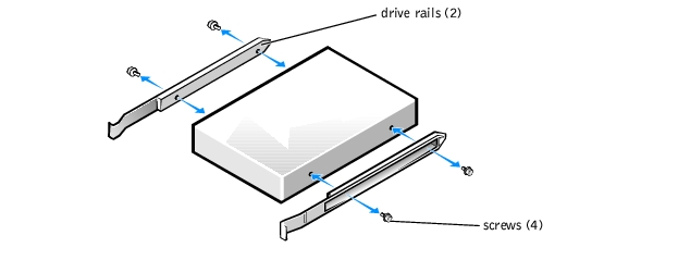
Figure 7-5. Installing Drive Rails
You must move the first IDE hard drive so you can easily connect the interface cable to the second drive in step 8.
If you are installing a second IDE drive, locate the middle connector on the interface cable that is attached to your first hard drive and attach that connector to the second hard drive.
See Figure A-3 for the location of the drive interface connectors on the system board.
See the documentation for your operating system for instructions.
See "Installing an Expansion Card" in "Installing System Components" for instructions about installing the card and routing the cables.
The system includes a standard diskette drive.
|
|
CAUTION: See your System Information Guide for complete information about safety precautions, working inside the computer, and protecting against electrostatic discharge. |
Figure 7-6. Removing or Installing a Diskette Drive
|
|
CAUTION: See your System Information Guide for complete information about safety precautions, working inside the computer, and protecting against electrostatic discharge. |
See Figure A-3 for the location of the diskette-drive interface connector on the system board.
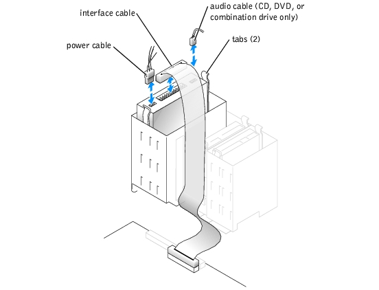
You can install an additional 5.25-inch drive of your choice in the second 5.25-inch drive bay. See Figure 7-1. If you are installing a tape backup unit (TBU), it must be installed in the second bay.
|
|
CAUTION: See your System Information Guide for complete information about safety precautions, working inside the computer, and protecting against electrostatic discharge. |
For instructions, see the documentation that accompanied the drive. Also, see "IDE Drive Installation Guidelines" for information on configuring the drive.
Figure 7-7. Installing a 5.25-Inch Drive