Back to Contents Page
Dell™ PowerEdge™ 6650 Systems
Service Manual
The procedures in this guide require that you remove the cover and work inside the system. While working inside the system, do not attempt to service the system except as explained in this manual and elsewhere in your system documentation. Always follow the instructions closely. Make sure to review all of the procedures in "Safety Instructions" in your System Information document.

|
CAUTION: Only trained service technicians are authorized to remove the system cover and access any of the components inside the system. See your System Information document for complete safety information. |
This section provides servicing procedures for components inside the system. Before you start any of the procedures in this section, perform the following tasks:
When there is no replacement procedure provided, use the removal procedure in reverse order to install the replacement part.
- Key to the system keylock
- Torx T15 driver
- 1/8-inch wide flat-tipped screwdriver
- 1/4-inch nut driver
- #1 and #2 Phillips screwdriver
- Wrist grounding strap
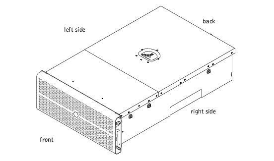
The illustrations in this document are based on the positioning of the system as shown in Figure 4-1.
Figure 4-1. System Orientation
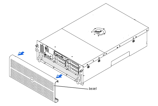
The bezel has status and caution indicators. Opening or removing the bezel provides access to the power switch, diskette drive, CD drive, and hard drive(s). You must open the bezel and remove the system covers to gain access to internal components.
To remove the bezel, pull the bezel away from the system (see Figure 4-2).
Figure 4-2. Removing the Bezel
- Align the bezel retaining clips with the retaining pins on the front of the system.
- Press the bezel to the system until it snaps into place.
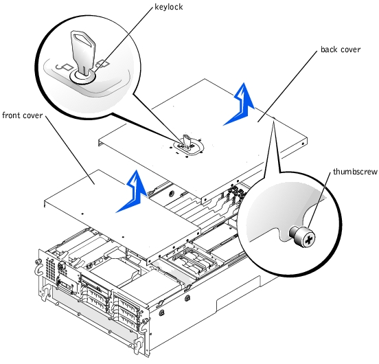
The system is enclosed by a bezel and two covers. To upgrade or service the system, remove the system covers to gain access to internal
components. The back cover must be removed before removing the front cover.
- Using the system key, unlock the back cover.
- Loosen the thumbscrew that secures the back cover to the chassis (see Figure 4-3).
- Slide the back cover backward and grasp the cover at both ends.
- Carefully lift the cover away from the system.
Figure 4-3. Removing and Replacing the Covers
- Ensure that no tools or parts are left inside the system and that any cables are routed
so that they will not be damaged by the cover.
- Align the cover with the cover alignment notches on the sides of the chassis, and slide
the cover forward (see Figure 4-3).
- Tighten the thumbscrew that secures the cover to the chassis.
- Using the system key, lock the back cover.
- Remove the back cover (see "Removing the Back Cover").
- Slide the front cover backward and grasp the cover at both ends (see Figure 4-3).
- Carefully lift the cover away from the system.
- Ensure that no tools or parts are left inside the system and that any cables are routed
so that they will not be damaged by the cover.
- Align the cover with the cover alignment notches on the sides of the chassis, and slide
the cover forward (see Figure 4-3).
- Replace the back cover (see "Replacing the Back Cover").
In Figure 4-4, the covers and bezel are removed to provide an interior view of the system.
Figure 4-4. Inside the System
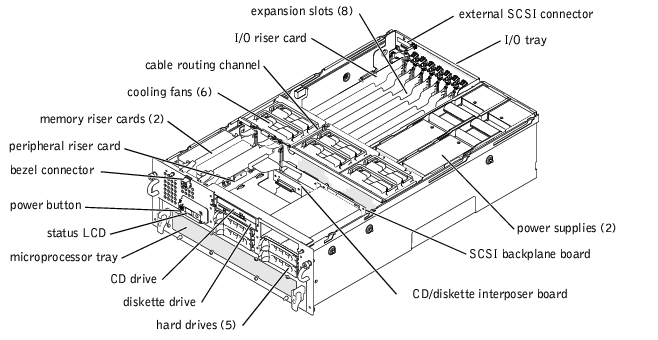
The I/O board can accommodate up to eight PCI expansion cards (seven PCI or PCI-X cards at 32- or 64-bit/33-100 MHz and one PCI card at 32-bit/33 MHz). The system memory is contained on two separate riser cards that must be populated with at least two memory modules each for the system to operate. The system provides space for a 3.5-inch diskette drive and a CD drive.
The PDB provides hot-plug logic, and power distribution for the system. The hot-pluggable power supplies that connect to the PDB provide power to the system and internal peripherals. Each hot-pluggable power supply has its own AC power input to provide AC power redundancy.
The hard-drive bays provide space for up to five 1-inch hard drives. The hard drives connect to a SCSI or RAID controller through the SCSI backplane board. Interface cables connect externally accessible SCSI devices and the SCSI backplane board to a SCSI controller on either the I/O riser card or a RAID controller card. For non-SCSI drives such as the diskette drive and CD drive, an interface cable connects the interposer board, attached to the CD/diskette drive tray, to the peripheral riser card (for more information, see "Hard Drives").
During an installation or service procedure, you may be required to change a jumper. For information on the system jumpers, see "Jumpers and Connectors."
The front panel LCD control panel provides status information using an alphanumeric character display.
|
|
CAUTION: Read the safety instructions in your System Information document. |
- Remove the bezel (see "Removing the Bezel").
- Remove the back cover (see "Removing the Back Cover").
- Remove the front cover (see "Removing the Front Cover").
- Remove the following control panel cables:
- The bezel connector cable
- The control-panel cable connected to the peripheral riser card
- Using a Torx T15 wrench, remove the four screws that secure the front-panel status
LCD to the front panel (see Figure 4-5).
Figure 4-5. Removing the Control Panel
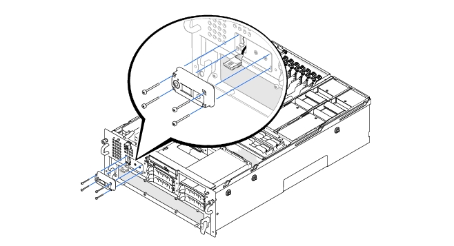
- Remove the control panel.
|
|
CAUTION: Read the safety instructions in your System Information document. |
- Align the control panel to the front panel.
- Using a T15 Torx wrench and the four screws you removed with the faulty control
panel, secure the control panel to the front panel ((see Figure 4-5).
- Reconnect the following cables:
- The bezel connector cable
- The control panel cable from the peripheral riser card connector CPCONN
- Replace the front cover (see "Removing the Front Cover").
- Replace the back cover (see "Replacing the Back Cover").
- Replace the bezel (see "Replacing the Bezel").
|
|
CAUTION: Read the safety instructions in your System Information document. |
- Remove the bezel (see "Removing the Bezel").
- Remove the back cover (see "Removing the Back Cover").
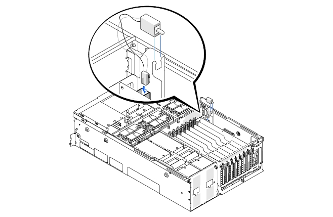
- Disconnect the chassis intrusion switch cable from the I/O riser card.
- Grasp the chassis intrusion switch and pull straight up to remove the switch from the
retaining bracket (see Figure 4-6).
Figure 4-6. Removing the Chassis Intrusion Switch
|
|
CAUTION: Read the safety instructions in your System Information document. |
- Slide the chassis intrusion switch down into the retaining bracket (see Figure 4-6).
- Connect the chassis intrusion switch cable to the INTR connector on the I/O riser
card (see Figure 5-2 for the location of the connector).
- Replace the back cover (see "Replacing the Back Cover").
- Replace the bezel (see "Replacing the Bezel").
The system includes six hot-pluggable cooling fans contained within a framed section of the chassis.
 |
NOTE: The procedure for replacing each individual fan is the same.
|
- Loosen the thumbscrew that secures the back cover to the chassis (see "Removing the
Back Cover").
- Slide the back cover backward to the service position.
The back cover service position allows you to remove and replace fans without removing the back cover.
 |
NOTICE: The cooling fans are hot-pluggable. To maintain proper cooling while the system is
on, replace only one fan at a time.
|
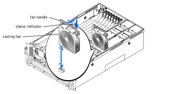
- Lift the fan handle and pull the fan straight up to clear the chassis (see Figure 4-7).
Figure 4-7. Removing and Installing a Cooling Fan
|
NOTE: The procedure for replacing each individual fan is the same.
|
|
NOTICE: Ensure that the memory riser card handles and the peripheral riser card handles are
in the closed position before installing a cooling fan.
|
- Lower the fan into the chassis until the fan snaps into position (see Figure 4-7).
- Lower the fan handle down to the installed position.
|
NOTE: After installing a new fan, allow up to 30 seconds for the system to recognize the
fan and determine whether it is working properly. The status indicator becomes green to
signify that the fan is functioning properly (see Figure 4-7).
|
- Slide the back cover forward.
- Tighten the thumbscrew that secures the back cover to the chassis (see "Replacing the
Back Cover").
The system includes two hot-pluggable power supplies. Only one power supply should be removed at a time when the system is running.
- Remove the back cover (see "Removing the Back Cover").
- Check the Power-Supply Indicator Codes. If the red fault indicator on one of the
power supplies is lit, that power supply is faulty and must be replaced.
- Disconnect the faulty power supply from its electrical outlet.
|
NOTICE: The power supplies are hot-pluggable. The system requires one power supply to be
installed for the system to operate normally. The system is in the redundant mode when two
power supplies are installed. Remove and replace only one power supply at a time in a system
that is powered on.
|
- Remove the power supply by lifting the power-supply handle and pulling the power
supply straight out of the chassis (see Figure 4-8).
Figure 4-8. Removing and Installing the Power Supply
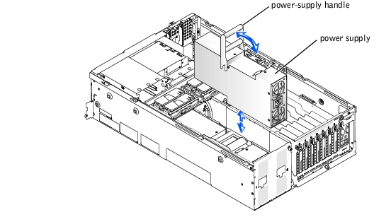
- Install the new power supply by lowering it into the chassis and pressing the handle
into place (see Figure 4-8).
- Lower the power-supply handle down to the installed position.
|
NOTE: After installing a new power supply, allow several seconds for the system to
recognize the power supply and determine whether it is working properly. The power-on
indicator becomes green to signify that the power supply is functioning properly (see
Figure 3-5).
|
- Replace the back cover (see "Replacing the Back Cover").
The system includes eight hot-pluggable expansion slots. Slot 1 operates at 33 MHz. Slots 2 through 8 are capable of operating at 33, 66, or 100 MHz. The expansion slots are on six different PCI buses (see Figure 5-3 for expansion-card buses and operating speeds).
- If you are installing a remote access card, it must be installed in slot 1. Slot 1 operates at 33 MHz.
- RAID controller cards must be installed in expansion slots 2 or 3.
- You can install expansion cards of different operating speeds on the same bus; however, all cards on the same bus will operate at the speed of the slowest card on that bus. For example, if one card on the bus has an operating speed of 66 MHz and the other card has an operating speed of 100 MHz, the bus will only operate at 66 MHz.
- To optimize performance, install only one expansion card on a single PCI bus. Otherwise, install only cards of the same operating speed on the same PCI bus. To identify PCI buses, see Figure 5-3.
- If you are replacing an expansion card with a card of a slower operating speed, you must power down the system to install the replacement card.
- If the expansion card you are installing is of a slower operating speed as the cards already installed on the same PCI bus, you must power down all expansion slots on that bus. This action will ensure that all expansion cards on that bus will power up at the same operating speed. Otherwise, you can install the expansion card in an expansion slot that is alone on a PCI bus or on a PCI bus having cards of the same or slower operating speeds. To identify PCI buses, see Figure 5-3.
- Certain operating systems only support "hot-replace," in which a hot-pluggable expansion card is replaced with its exact equivalent, using the same PCI resources.
- If you are hot-plugging a NIC expansion card, you must either hot-plug the NIC card in an expansion slot that is alone on a PCI bus or on a PCI bus having no card other than another NIC. To identify PCI buses, see Figure 5-3.
- If you have trouble hot-plugging a particular expansion card, turn off your system before installing the card. If the problem persists, see "Obtaining Technical Assistance."
The system's BIOS scans and numbers PCI buses and devices during startup. Expansion slots are scanned according to the host bus ordering, not by the slot numbers. See Table 4-1 for the order in which the expansion slots and embedded PCI devices are scanned. Figure 5-3 provides a diagram of buses and expansion slots.
Several additional factors affect the assignment of PCI bus numbers:
- An expansion card may have its own PCI bridge chip which requires the assignment of a bus number for the card and one for the bridge. A particular expansion card may have two PCI bridge chips which would result in three sequential PCI bus numbers all assigned in the same expansion slot.
- BIOS reserves PCI bus numbers that can be used when a hot-pluggable expansion card having its own PCI bridge chip is installed in the system.
Certain operating systems do not allow the PCI bus number of the system's boot controller to change after the operating system loads. Installing an expansion card with its own PCI bridge chip in an expansion slot earlier in the PCI bus scan order than the boot controller can cause the renumbering of the boot controller PCI bus number.
To allow your operating system to properly utilize the boot controller expansion card, install the boot controller card, such as a RAID or SCSI controller card, in expansion slot 2.
If you install expansion cards, you may have some difficulty in directly determining the bus number of a controller on a particular expansion card. However, the PCI bus scan order listed in Table 4-1 can help determine the relative numbering of PCI buses within the expansion slots. For example, a PCI controller residing in expansion slot 3 will never have a lower bus number than one in slot 2 because slot 2 precedes slot 3 in the scan order.
Table 4-1. PCI Bus Scan Order
|
Order
|
Device or Expansion Slot
|
|---|
1 | Integrated SCSI controller on the I/O riser card |
2 | Video |
3 | Expansion slot 1 |
4 | Expansion slot 2 |
5 | Expansion slot 3 |
6 | Integrated NIC 1 |
7 | Integrated NIC 2 |
8 | Expansion slot 6 |
9 | Expansion slot 4 |
10 | Expansion slot 5 |
11 | Expansion slot 8 |
12 | Expansion slot 7 |
|
|
|
CAUTION: If your operating system does not support hot-plug PCI or PCI-X expansion cards or the expansion card itself does not support hot-plug removal, turn off the system, including any attached peripherals, and disconnect the system from its electrical outlet. |
|
|
CAUTION: See "Protecting Against Electrostatic Discharge" in the safety instructions in your System Information document. |
- Remove the back cover (see "Removing the Back Cover").
- If your operating system does not support hot-plug expansion cards, turn off the
system, including any attached peripherals, and disconnect the system from its
electrical outlet.
If your operating system does support hot-plug expansion cards, press the notify button next to the expansion slot and wait until the status indicator turns off.
- Disconnect any cables connected to the card.
- To release the expansion card:
- Grasp the card-guide latch tab and pull it away from the system (see Figure 4-9).
- Press and hold the plastic tab on the outside of the system.
- Press the release tab on the expansion-card latch inside the system (see
Figure 4-9).
- Open the expansion-card latch.
- Grasp the expansion card by its top corners, and carefully remove it from the
expansion-card connector.
- If you are removing the card permanently, install a metal filler bracket over the empty
expansion slot opening.
|
NOTE: You must install a filler bracket over an empty expansion slot to maintain Federal
Communications Commission (FCC) certification of the system. The brackets also keep dust
and dirt out of the system and aid in proper cooling and airflow inside the system.
|
- Replace the back cover (see "Replacing the Back Cover").
If you turned off your system in step 2 due to your operating system's not supporting hot-plug expansion cards, replace the system back cover, reconnect the system to its electrical outlet, including any attached peripherals, and turn on the system.
|
|
CAUTION: If your operating system does not support hot-plug PCI or PCI-X expansion cards or the expansion card itself does not support hot-plug removal, turn off the system, including any attached peripherals, and disconnect the system from its electrical outlet. |
|
|
CAUTION: See "Protecting Against Electrostatic Discharge" in the safety instructions in your System Information document. |
- Remove the back cover (see "Removing the Back Cover").
See the documentation that came with the expansion card for information on configuring the card, making internal connections, or otherwise customizing the card for your system.
- Open the expansion-card latch:
- Press and hold the plastic tab on the outside of the system chassis.
- Press the release tab on the expansion-card latch inside the system chassis (see
Figure 4-9).
- Open the expansion-card latch and remove the filler bracket.
- If your operating system does not support hot-plug expansion cards, turn off the
system, including any attached peripherals, and disconnect the system from its
electrical outlet.
If your operating system does support hot-plug expansion cards, press the expansion slot notify button and wait until the status indicator turns green (see "Expansion-Slot Indicator Codes" in "Indicators, Codes, and Error Messages" for information on expansion slot status).
- Install the expansion card (see Figure 4-9).
- Position the expansion card so that the card-edge connector aligns with the
expansion-card connector on the I/O board.
- Insert the card-edge connector firmly into the expansion-card connector until the
card is fully seated.
Figure 4-9. Installing an Expansion Card
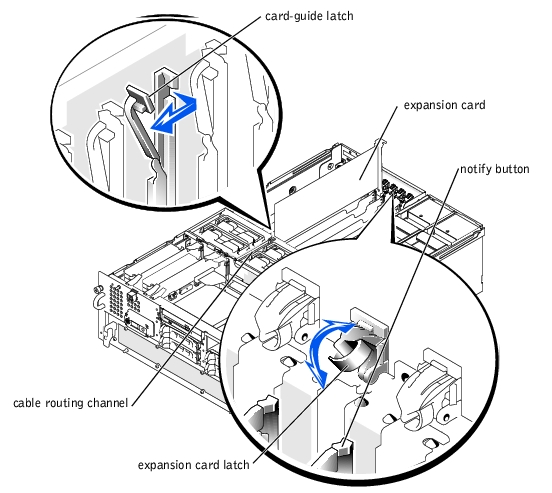
- When the card is seated in the connector, close the expansion-card latch and the card-
guide latch (see Figure 4-9).
- Connect any cables that should be attached to the card.
See the documentation that came with the card for information about its cable connections.
|
NOTE: Route the SCSI cables connected from an expansion card to the SCSI backplane
board through the cable-routing channel in the cooling-fan bracket (see Figure 4-9).
|
|
NOTE: If the expansion card you are installing is of a slower operating speed as the cards
already installed on the same PCI bus, you must power down all expansion slots on that bus.
This action will ensure that all expansion cards on that bus will power up at the same
operating speed.
|
- Press the notify button for the expansion card that you installed and wait until the
status indicator turns green.
If you turned off your system in step 3 due to your operating system's not supporting hot-plug expansion cards, replace the back cover, reconnect the system to its electrical outlet, including any attached peripherals, and turn on the system.
- Replace the back cover (see "Replacing the Back Cover" in "Troubleshooting Your
System").
The I/O riser card provides the communication signals for an external SCSI device, the chassis intrusion switch, and the back-panel status indicator, as well as external devices connected to the system back panel. The I/O riser card also contains the system configuration jumpers and the embedded server management processor.
- Turn off the system, including any attached peripherals, and disconnect the system
from the electrical outlet.
- Remove the back cover (see "Removing the Back Cover").
- Disconnect the I/O riser card cables (see Figure 4-10):
- External devices from the system back panel connectors
- The back-panel status indicator cable from the P1 connector
- The SCSI cable from the SCSI connector
- The intrusion switch cable from the INTR connector
Figure 4-10. Removing and Replacing the I/O Riser Card

- If applicable, loosen the thumbscrew that secures the external SCSI connector to the
back panel and remove the connector (see Figure 4-10).
- Loosen the thumbscrew that secures the I/O riser card to the back panel (see
Figure 4-10).
- Carefully lift the I/O riser card straight up to clear the system.
- Carefully lower the I/O riser card into the system while aligning the card-edge
connectors with the connectors on the I/O card.
- Insert the card connectors firmly into the I/O board connectors until the card is fully
seated.
- Tighten the thumbscrew that secures the I/O riser card to the back panel.
- Replace the external SCSI connector and tighten the thumbscrew that secures the
connector to the back panel.
- Connect the following cables (see Figure 4-10):
- External devices to the system back panel connectors
- The back-panel status indicator cable to the P1 connector
- The SCSI cable to the SCSI connector
- The intrusion switch cable to the INTR connector
- Replace the back cover (see "Replacing the Back Cover").
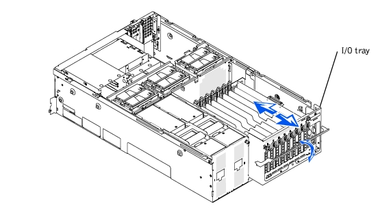
The I/O tray can be removed to access certain components such as the I/O board and the 5-V power supply VRM. See Figure 5-3 to identify the I/O board components.
|
|
CAUTION: Before you perform this procedure, you must turn off the system and disconnect it from its power source. |
|
|
CAUTION: See "Protecting Against Electrostatic Discharge" in the safety instructions in your System Information document. |
- Turn off the system, including any attached peripherals, and disconnect the system
from the electrical outlet.
- Remove the back cover (see "Removing the Back Cover").
- Disconnect the following cables:
- External devices from the system back panel connectors
- The SCSI cable from the I/O riser card SCSI connector if the cable is connected to the SCSI backplane (see Figure 5-2)
- Expansion-card cables
- Loosen the thumbscrew that secures the I/O tray handle to the back panel (see
Figure 4-12).
- Rotate the I/O tray handle up until the tray is released from the chassis (see
Figure 4-12).
Lift the I/O tray handle and pull the tray out of the chassis (see Figure 4-11).
Figure 4-11. Removing and Installing the I/O Tray
|
|
CAUTION: Before you perform this procedure, you must turn off the system and disconnect it from its power source. |
|
|
CAUTION: See "Protecting Against Electrostatic Discharge" in the safety instructions in your System Information document. |
- Slide the I/O tray into the chassis until the tray stops.
- Rotate the I/O tray handle down until the tray is secured in the chassis (see
Figure 4-11).
- Connect all expansion card cables.
- Connect the following cables:
- External devices to the system back panel connectors
- The SCSI cable to the I/O riser card SCSI connector if the cable is connected to the SCSI backplane (see Figure 5-2)
- Expansion-card cables
- Replace the back cover (see "Replacing the Back Cover").
|
|
CAUTION: Read the safety instructions in your System Information document. |
- Remove the bezel (see "Removing the Bezel").
- Turn off the system, including any attached peripherals, and disconnect the system
from the electrical outlet.
- Remove the back cover (see "Replacing the Back Cover").
- Slide the microprocessor tray out until the safety latches lock into place (see
"Removing the Microprocessor Tray").
- Remove the I/O riser card (see "Removing the I/O Riser Card").
- Remove all installed expansion cards (see "Removing an Expansion Card").
- Remove the 5-V VRM from the I/O board.
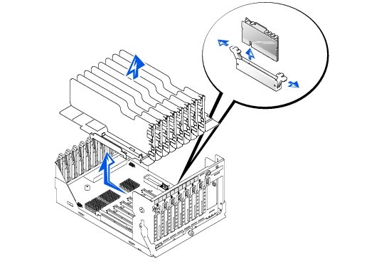
- Using a 1/8-inch flat-tipped screwdriver, release the latches that secure the
expansion-card insulator to the sides of the I/O tray (see Figure 4-12).
- Remove the expansion-card insulator from the chassis.
Figure 4-12. Removing the Expansion-Card Insulator and I/O Board
|
|
CAUTION: Read the safety instructions in your System Information document. |
- Align the expansion-card insulator so that the insulator slides down over the I/O board
connectors.
- Push the expansion-card insulator down so that the insulator clips snap onto the sides
of the I/O tray.
- Replace the 5-V VRM that you removed.
- Replace any expansion cards that you removed (see "Removing an Expansion Card").
- Replace the I/O riser card (see "Removing the I/O Riser Card").
- Slide the I/O tray into the chassis until the tray stops (see "Removing the I/O Tray").
- Lift the I/O tray handles up and push the tray forward slightly to engage the handle
latches.
- Rotate the microprocessor tray handle down and secure the handle with its
thumbscrew to the back panel.
- Replace the back cover (see "Replacing the Back Cover").
- Replace the bezel (see "Replacing the Bezel").
|
|
CAUTION: Read the safety instructions in your System Information document. |
- Remove the expansion-card insulator (see "Removing the Expansion-Card Insulator").
- Loosen the thumbscrew that secures the I/O board to the I/O tray (see Figure 4-12).
- Slide the I/O board toward the front of the system about 0.5 inch.
- Lift the front of the I/O board off of its grounding tabs and then remove the I/O board
out from I/O tray (see Figure 4-12).
|
|
CAUTION: Read the safety instructions in your System Information document. |
- Align the I/O board with the grounding tabs on the floor of the I/O tray.
- Slide the I/O board toward the back of the system about 0.5 inch.
- Tighten the thumbscrew that secures the I/O board to the I/O tray (see Figure 4-12).
- Replace the expansion-card insulator (see "Expansion-Card Insulator and I/O Board").
- Replace the I/O tray (see "Replacing the I/O Tray").
The peripheral riser card provides the communication signals for the CD/diskette assembly and the control panel, and power for the SCSI backplane board.
- Turn off the system, including any attached peripherals, and disconnect the system
from the electrical outlet.
- Loosen the thumbscrew that secures the back cover to the chassis (see "Removing the
Back Cover").
- Slide the back cover backward to the service position.
The back cover service position allows you to remove and replace fans without removing the back cover.
- Remove the front cover (see "Removing the Front Cover").
- Disconnect the peripheral riser card cables (see Figure 4-13):
- Control panel cable from the CPCONN connector
- CD/diskette cable from the CDFDCONN connector
- SCSI backplane board power cable from the BPCONN connector
Figure 4-13. Removing and Installing the Peripheral Riser Card
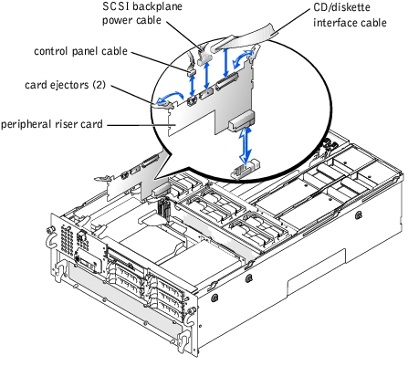
- Grasp the peripheral riser card ejectors, and rotate the ejectors up to release the card
from the microprocessor board (see Figure 4-13).
- Lift the peripheral riser card straight up to clear the chassis.
- Position the peripheral riser card so that the card connector is aligned with the
connector on the microprocessor board (see Figure 5-4 to identify the microprocessor
board connector).
- Lower the card into the chassis until the ejectors are in the peripheral riser card guides
(see Figure 4-13).
- Rotate the ejectors down until the until the card is fully seated.
- Connect the following cables (see Figure 4-13):
- Control panel cable to the CPCONN connector
- CD/diskette cable to the CDFDCONN connector
- SCSI backplane board power cable to the BPCONN connector
- Replace the front cover (see "Replacing the Front Cover").
- Slide the back cover forward.
- Tighten the thumbscrew that secures the back cover to the chassis (see "Replacing the
Back Cover").
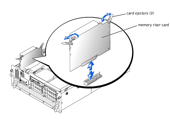
The system contains two memory riser cards. Each card contains up to eight memory modules.
|
|
CAUTION: Before you perform this procedure, you must turn off the system and disconnect it from its power source. |
|
|
CAUTION: See "Protecting Against Electrostatic Discharge" in the safety instructions in your System Information document. |
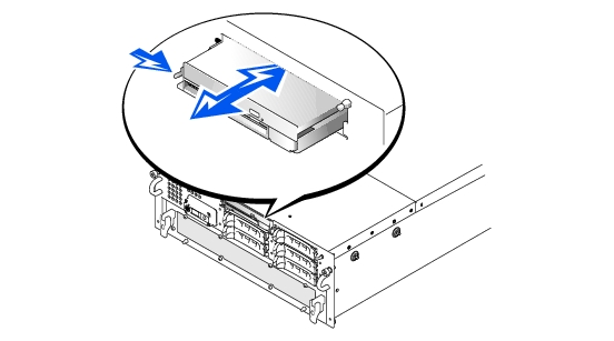
- Turn off the system, including any attached peripherals, and disconnect the system
from the electrical outlet.
- Loosen the thumbscrew that secures the back cover to the chassis (see "Removing the
Back Cover").
- Slide the back cover backward to the service position.
The back cover service position allows you to remove and replace fans without removing the back cover.
- Remove the front cover (see "Removing the Front Cover").
- Grasp the memory riser card ejectors, and rotate the ejectors up to release the card
from the microprocessor card (see Figure 4-14).
- Lift the memory riser card straight up to clear the chassis.
Figure 4-14. Removing and Replacing Memory Riser Cards
|
|
CAUTION: Read the safety instructions in your System Information document. |
|
|
CAUTION: See "Protecting Against Electrostatic Discharge" in the safety instructions in your System Information document. |
- Position the memory riser card so that the card connector is aligned with the
connector on the microprocessor board (see Figure 5-4 to identify the microprocessor
board connectors).
- Lower the card into the chassis until the ejectors are in the memory riser card guides
(see Figure 4-15).
- Rotate the ejectors down until the card is fully seated.
- Replace the front cover (see "Replacing the Front Cover" in "Troubleshooting Your
System").
- Slide the back cover forward.
- Tighten the thumbscrew that secures the back cover to the chassis (see "Replacing the
Back Cover").
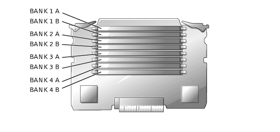
The memory modules are contained on two memory riser cards. Each riser card has eight memory module sockets. Between the two memory riser cards, the system can accommodate 512 MB to 16 GB of registered memory modules. The memory module sockets on each riser card are arranged in pairs (A and B) on four banks (1–4). Two sockets on each riser card compose one bank (see Figure 4-15). Each bank must contain four identical memory modules. For example, if bank 1 sockets on one riser card contain 128-MB memory modules, bank 1 sockets on the other riser card must also contain 128-MB memory modules. For the system to operate, at least bank 1 must contain four identical memory modules. The memory modules must be installed starting with bank 1 and ending with bank 4 (see Figure 4-15).
To obtain the desired total memory for your system, you may need to install memory modules of different sizes. This configuration is supported as long as the memory modules installed in each bank are the same size. For example, if you wanted the total memory in your system to be 6 GB, each memory riser card configuration could be as follows:
The system is upgradable to 16 GB by installing combinations of 128-, 256-, 512-MB, and 1-GB registered memory modules. You can purchase memory upgrade kits as needed.
|
NOTE: The memory modules must be PC-1600 compliant.
|
Memory module sockets are arranged in pairs, labeled A and B, on each memory riser card. A pair of sockets on each memory riser card forms a single memory bank. See Figure 4-15 to identify the sockets on a memory riser card.
When you install memory modules, follow these guidelines:
- Each bank must contain identical modules. You must install memory modules in matched sets of four, two in each memory riser card (see Figure 4-15).
- Install identical memory modules in sockets A and B for bank 1 before installing modules in sockets for bank 2, and so on.
- If you are populating memory banks using differently sized memory modules, you must populate the memory banks in decreasing size of memory modules starting with the largest size of memory modules in bank 1.
- Memory banks must be populated sequentially, which means that there can be no empty banks between the first and last populated banks.
Figure 4-15. Memory Module Sockets
|
NOTE: Table 4-3 is a sample configuration of just one memory riser card. For the total
desired memory, you must configure both riser cards identically with the same memory module
sizes.
|
Table 4-3. Sample Memory Module Configurations
|
Total Desired
Memory
|
Bank 1
|
Bank 2
|
Bank 3
|
Bank 4
|
|---|
|
A
|
B
|
A
|
B
|
A
|
B
|
A
|
B
|
|---|
512 MB | 128 MB | 128 MB | None | None | None | None | None | None |
1 GB | 128 MB | 128 MB | 128 MB | 128 MB | None | None | None | None |
1 GB | 256 MB | 256 MB | None | None | None | None | None | None |
2 GB | 512 MB | 512 MB | None | None | None | None | None | None |
4 GB | 512 MB | 512 MB | 512 MB | 512 MB | None | None | None | None |
6 GB | 1 GB | 1 GB | 512 MB | 512 MB | None | None | None | None |
12 GB | 1 GB | 1 GB | 1 GB | 1 GB | 1 GB | 1 GB | None | None |
14 GB | 1 GB | 1 GB | 1 GB | 1 GB | 1 GB | 1 GB | 512 MB | 512 MB |
16 GB | 1 GB | 1 GB | 1 GB | 1 GB | 1 GB | 1 GB | 1 GB | 1 GB |
|
|
CAUTION: See "Protecting Against Electrostatic Discharge" in the safety instructions in your System Information document. |
- Turn off the system, including any attached peripherals, and disconnect the system
from the electrical outlet.
- Remove the memory riser cards (see "Removing a Memory Riser Card").
- Install or replace the memory module pairs on each memory riser card as necessary to
reach the desired memory total (see "Performing a Memory Upgrade" and "Removing
Memory Modules").
See Figure 4-15 for the memory module socket locations on each memory riser card.
- Replace the memory riser cards (see "Replacing the Memory Riser Cards").
- Reconnect your system and peripherals to their electrical outlets, and turn on the
system.
After the system completes the POST routine, it runs a memory test.
The system detects that the new memory does not match the system configuration information, which is stored in NVRAM. The monitor displays an error message that ends with the following words:
Press <F1> to continue; <F2> to enter System Setup
- Press <F2> to enter the System Setup program, and check the System Memory
setting in the system data box.
The system should have already changed the value in the System Memory setting to reflect the newly installed memory.
- If the System Memory value is incorrect, one or more of the memory modules may not
be installed properly. Repeat steps 1 through 4, checking to make sure that the
memory modules are firmly seated in their sockets.
- Run the system memory test in system diagnostics.
|
|
CAUTION: See "Protecting Against Electrostatic Discharge" in the safety instructions in your System Information document. |
- Turn off the system, including any attached peripherals, and disconnect the system
from the electrical outlet.
- Remove the memory riser cards (see "Removing a Memory Riser Card").
- Locate the memory module sockets on each memory riser card in which you will install
a memory module (see Figure 4-15).
- Press down and outward on the memory module socket ejectors, as shown in
Figure 4-16, to allow the memory module to be inserted into the socket.
Figure 4-16. Removing and Installing a Memory Module
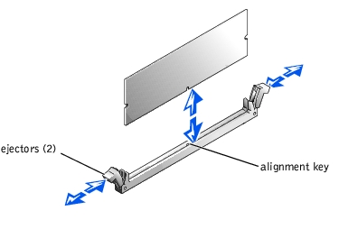
- Align the memory module's edge connector with the alignment key, and insert the
memory module in the socket (see Figure 4-16).
The memory module socket has an alignment key that allows the memory module to be installed in the socket in only one way.
- Press down on the memory module with your thumbs while pulling up on the ejectors
with your index fingers to lock the memory module into the socket (see Figure 4-16).
When the memory module is properly seated in the socket, the memory module socket ejectors should align with the ejectors on the other sockets with memory modules installed.
- Repeat steps 2 through 5 of this procedure to install the remaining memory modules.
- Perform steps 3 through 7 of the procedure in "Performing a Memory Upgrade."
|
|
CAUTION: See "Protecting Against Electrostatic Discharge" in the safety instructions in your System Information document. |
- Turn off the system, including any attached peripherals, and disconnect the system
from the electrical outlet.
- Remove the memory riser cards (see "Removing a Memory Riser Card").
- Locate the memory module sockets on each memory riser card in which you will
remove memory modules (see Figure 4-15).
- Press down and outward on the memory module socket ejectors until the memory
module pops out of the socket (see Figure 4-16).
- Remove the bezel (see "Removing the Bezel").
- Turn off the system, including any attached peripherals, and disconnect the system
from its electrical outlet.
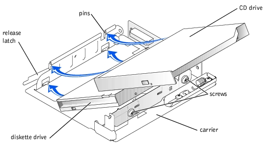
Figure 4-17. Replacing the CD and Diskette Drives
- Press the CD/diskette drive carrier release tab to release the carrier from the mating
connector in the system (see Figure 4-17).
The CD/diskette drive pops out of its slot about one inch.
- Slide the CD/diskette forward and remove it from the system.
- Using a 1/8-inch wide flat-tipped screwdriver, and loosen the plastic expansion
fasteners that secure the interposer board to the back of the carrier.
- Gently pull the interposer board away from the CD drive just far enough to release the
connector on the CD drive.
- Using a 1/4-inch nut driver or a Phillips screwdriver, loosen the two hex-head screws
located on the right side of the carrier using one full turn.
- Rotate the CD drive up and to the left, away from the carrier.
- Carefully remove the flat-ribbon cable from the back of the diskette drive.
Do not disconnect the back end of the ribbon cable from the interposer board.
|
NOTE: If you are replacing the CD drive, it is not necessary to remove the diskette drive
from the carrier.
|
- Rotate the diskette drive up and to the left, away from the carrier (see Figure 4-18).
Figure 4-18. Removing the CD and Diskette Drives From the Carrier
|
NOTE: If you are installing a replacement CD drive, and you did not remove the diskette
drive from the carrier, begin at step 4.
|
- Install the diskette drive into the CD/diskette drive carrier by lowering the left side
into the carrier with the pins aligned with holes on the side of the diskette drive (see
Figure 4-18).
- Lower the right side of the diskette drive into the carrier.
- Install the flat-ribbon cable on the interposer board into the connector on the back of
the diskette drive.
- Install the CD drive into the CD/diskette drive carrier by lowering the left side into
the carrier with pins on the side of the carrier aligned with holes on the left side of the
CD drive.
- Lower the right side into the carrier, and align the pins on the loosened plate assembly
with holes on the right side of the CD drive.
- Tighten the two hex-head screws on the right side of the carrier using a 1/4-inch nut
driver or Phillips screwdriver.
- Press the interposer board into its connector on the CD drive.
- Align the interposer board with the bracket on the CD/diskette drive carrier.
- Install the two expandable fasteners through the interposer board and into the holes in
the bracket. Install the plugs to secure the fastener.
- Align the CD/diskette drive carrier with the opening in the front panel.
- Slide the CD/diskette drive carrier until the carrier snaps into place.
- Connect the system to an electrical outlet and turn on the system, including any
attached peripherals.
- Replace the bezel (see "Replacing the Bezel").
If you are installing a SCSI tape drive in the peripheral bay, you must connect it to the I/O riser card. If you are installing SCSI hard drives in the peripheral bay, you must connect the interface cable from the peripheral bay's daughter card to a RAID controller card.
These interface connectors are keyed for correct insertion. Keying ensures that the pin-1 wire in the cable connects to pin 1 in the connectors on both ends.
When you disconnect an interface cable, take care to grasp the cable connector, rather than the cable itself, to avoid stress on the cable.
Although SCSI devices are installed in essentially the same way as other devices, their configuration requirements are different. To configure a SCSI device installed in the peripheral bay, follow the guidelines in the following subsections.
Each device attached to a SCSI host adapter must have a unique SCSI ID number from 0 to 15.
A SCSI tape drive is configured as SCSI ID 6 (the default ID number for a tape drive).
|
NOTE: It is not required that SCSI ID numbers be assigned sequentially or that
devices be attached to the cable according to ID number.
|
SCSI logic requires that the two devices at opposite ends of the SCSI chain be terminated and that all devices in between be unterminated. The SCSI cable included in the upgrade kit has an active terminator installed at the end of the cable. Therefore, when configuring the devices in the peripheral bay, you should disable the device's termination.
This subsection describes how to remove or replace and configure hard drives in the system's internal hard-drive bays and how to install or replace a RAID controller card.
The hard-drive bays provide space for up to five 1-inch hard drives. The hard drives connect to a SCSI or RAID controller through the backplane board. Interface cables connect the backplane board to a SCSI controller on either the I/O riser card or a RAID controller card.
Before attempting to remove or install a drive while the system is running, see the documentation for the RAID controller card to ensure that the card is configured correctly to support hot-pluggable drive removal and insertion.
Hard drives are supplied in special drive carriers that fit into the hard-drive bays.
|
NOTE: You should use only drives that have been tested and approved for use with this
system.
|
You may need to use different programs than those provided with the operating system to partition and format hard drives. See "Installing and Configuring SCSI Drivers" in the User's Guide for information and instructions.
|
NOTICE: Do not turn off or reboot your system while the drive is being formatted. Doing so can
cause a drive failure.
|
When you format a high-capacity hard drive, allow enough time for the formatting to be completed. Long format times for these drives are normal. For example, an exceptionally large drive can take over an hour to format.
|
NOTICE: When installing a hard drive, ensure that the adjacent drives are fully installed.
Inserting a hard-drive carrier and attempting to lock its handle next to a partially installed
carrier can damage the partially installed carrier's shield spring and make it unusable.
|
|
NOTICE: Not all operating systems support hot-plug drive installation. See the documentation
supplied with your operating system.
|
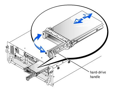
- Remove the bezel (see "Removing the Bezel").
- Open the hard-drive carrier handle (see Figure 4-19).
Figure 4-19. Installing a Hard Drive
|
NOTICE: Do not insert a hard-drive carrier and attempt to lock its handle next to a partially
installed carrier. Doing so can damage the partially installed carrier's shield spring and make it
unusable. Ensure that the adjacent drive carrier is fully installed.
|
- Insert the hard-drive carrier into the drive bay.
- Close the hard-drive carrier handle to lock it in place (see Figure 4-19).
- Replace the bezel (see "Replacing the Bezel").
|
NOTICE: Not all operating systems support hot-plug drive installation. See the documentation
supplied with your operating system.
|
- Remove the bezel (see "Removing the Bezel").
- Take the hard drive offline and wait until the hard-drive indicator codes on the drive
carrier signal that the drive may be removed safely.
If the drive has been online, the drive status indicator blinks green two times per second as the drive is powered down. When all indicators are off, the drive is ready for removal.
See your operating system documentation for more information about taking the hard drive offline.
- Open the hard-drive carrier handle to release the drive (see Figure 4-19).
- Slide the hard drive out until it is free of the drive bay (see Figure 4-19).
If you are permanently removing the hard drive, install a blank insert.
- Replace the bezel (see "Replacing the Bezel").
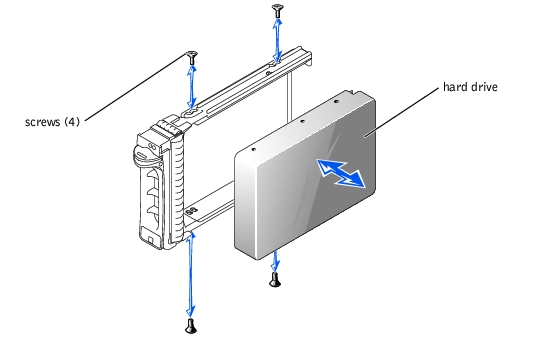
- If your replacement hard drive does not have a carrier, remove the faulty hard drive
from its carrier:
- Remove the four screws that secure the drive to the carrier (see Figure 4-20).
- Remove the hard drive from the carrier.
- Install the replacement hard drive in the carrier and secure it with the four screws
you removed when you removed the faulty hard drive.
Figure 4-20. Removing the Hard Drive From the Carrier
The hard-drive bays provide space for up to five 1-inch hard drives. These hard drives are connected to the integrated SCSI controller through the backplane board. If a RAID controller is installed, it is connected to the backplane board.
|
|
CAUTION: Read the safety instructions in your System Information document. |
- Remove the bezel (see "Removing the Bezel").
- Turn off the system, including any attached peripherals, and disconnect the system
from the electrical outlet.
- Pull the hard drives out of their slots approximately 5 mm (2 inches) (see "Removing a
Hard Drive").
- Remove the back cover (see "Removing the Back Cover").
- Remove the front cover (see "Removing the Front Cover").
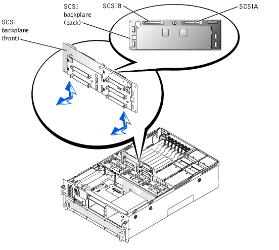
- Disconnect the following backplane cables:
- The DC power connector from the PWRCONN connector
- The SCSI cable from the SCSIA connector
- The SCSI cable from the SCSIB connector, if applicable.
- Loosen the thumbscrew that secures the SCSI backplane to the chassis (see
Figure 4-21).
- Slide the backplane upwards about 0.5 inch), pull the SCSI backplane away, off of its
grounding tabs (toward the back of the system), and out of the system chassis (see
Figure 4-21).
Figure 4-21. Replacing the SCSI Backplane Board
|
|
CAUTION: Read the safety instructions in your System Information document. |
- Align the replacement backplane with the grounding tabs inside the chassis.
- Slide the backplane about 0.5 inch.
- Tighten the thumbscrew that secures the backplane to the chassis (see Figure 4-12).
- Reconnect the following backplane cables:
- The DC power connector from the PWRCONN connector
- The SCSI cable from the SCSIA connector
- The SCSI cable from the SCSIB connector, if applicable
- Install the hard drives into their slots in the drive bay (see "Hard Drives").
- Replace the front cover (see "Replacing the Front Cover").
- Replace the back cover (see "Replacing the Back Cover").
- Close the bezel (see "Replacing the Bezel").
This subsection describes how to configure and install an external SCSI tape drive.
|
|
CAUTION: Read the safety instructions in your System Information document. |
|
|
CAUTION: See "Protecting Against Electrostatic Discharge" in the safety instructions in your System Information document. |
- Turn off the system, including any attached peripherals, and disconnect the system
from the electrical outlet.
- Prepare the tape drive for installation.
Ground yourself by touching an unpainted metal surface on the back of the system, unpack the drive and controller card, and compare the jumper and switch settings with those in the drive documentation.
See "SCSI Configuration Information" for information on setting the drive's SCSI ID number and enabling termination (if required). Change any settings necessary for your system's configuration.
- Connect the tape drive's interface cable to the external SCSI connector on the back of
the system.
- Secure the connection by tightening the screws on the external SCSI connector.
- Reconnect the system and peripherals to electrical outlets, and turn them on.
- Perform a tape backup and verification test with the drive as instructed in the software
documentation that came with the drive.
Follow these general guidelines when installing a RAID controller card. For specific instructions, see the documentation supplied with the controller card.
|
|
CAUTION: Read the safety instructions in your System Information document. |
|
|
CAUTION: See "Protecting Against Electrostatic Discharge" in the safety instructions in your System Information document. |
- Unpack the RAID controller card, and prepare it for installation.
For instructions, see the documentation accompanying the card.
- Remove the microprocessor tray (see "Removing the Microprocessor Tray").
- Install the RAID controller card (see "Installing an Expansion Card").
If you are connecting the card to internal drives, install the RAID controller card in expansion slot 2 or 3.
- Connect the SCSI interface cable as follows, routing it under the fan assembly tray:
- To operate the SCSI backplane in a 1 x 8 configuration, connect the interface cable to the SCSIA connector on the SCSI backplane board and to the RAID controller card.
- To operate the SCSI backplane in a 2 x 4 configuration, connect the interface cable to the SCSIB connector on the SCSI backplane board and to the RAID controller card.
To identify the correct RAID controller card connector, see the documentation for the card.
- Replace the microprocessor tray (see "Replacing the Microprocessor Tray").
- Reconnect the system to an electrical outlet and turn it on.
- Install any required SCSI device drivers (see "Installing and Configuring SCSI Drivers"
in the User's Guide).
- Test the SCSI devices.
Test a SCSI hard drive by running the SCSI Controllers test in the system diagnostics.
The microprocessor tray must be removed to access the microprocessors and VRMs. See Figure 5-4 and Table 5-4 to identify the microprocessor board components.
|
|
CAUTION: Read the safety instructions in your System Information document. |
|
|
CAUTION: See "Protecting Against Electrostatic Discharge" in the safety instructions in your System Information document. |
- Remove the bezel (see "Removing the Bezel").
- Turn off the system, including any attached peripherals, and disconnect the system
from the electrical outlet.
- Remove the back cover (see "Removing the Back Cover").
- Remove the front cover (see "Removing the Front Cover").
- Raise the following components to the service position:
- Press the release clip and rotate the microprocessor tray handles up until the tray
releases from the front panel (see Figure 4-22).
Figure 4-22. Removing and Replacing the Microprocessor Tray
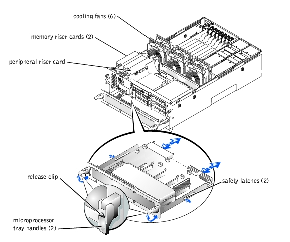
- Slide the microprocessor tray out until the tray's safety latches lock into place.
- While pressing the safety latches, pull the microprocessor tray straight out until the
tray clears the chassis.
|
|
CAUTION: Read the safety instructions in your System Information document. |
|
|
CAUTION: See "Protecting Against Electrostatic Discharge" in the safety instructions in your System Information document. |
- Slide the microprocessor tray into the chassis until the tray stops.
- Lift the microprocessor tray handles up and push the tray forward slightly to engage
the handle clasps.
- Rotate the microprocessor tray handles down until the tray is secured to the front
panel (see Figure 4-22).
- Reseat the following components:
- Cooling fans (see "Replacing a Cooling Fan").
- Replace the front cover (see "Replacing the Front Cover").
- Replace the back cover (see "Replacing the Back Cover").
- Replace the bezel (see "Replacing the Bezel").
Two types of VRMs are contained in your system:
- A microprocessor VRM for each processor installed in the system
- A 5-V power supply VRM installed in the I/O tray
|
|
CAUTION: See "Protecting Against Electrostatic Discharge" in the safety instructions in your System Information document. |
- Turn off the system, including any attached peripherals, and disconnect the system
from the electrical outlet.
- Identify the VRM connector on the I/O board (see Figure 5-3).
- Press down and outward on the VRM connector ejectors until the VRM pops out of
the socket (see Figure 4-23).
- If you removed the I/O tray, replace the tray ("Replacing the I/O Tray").
- Replace the back cover (see "Replacing the Back Cover").
The system is designed to allow access to the 5-V power supply VRM without removing other components from the system. However, you can remove the I/O tray to provide easier access to the 5-V power supply VRM (see "Removing the I/O Tray").
|
|
CAUTION: Before you perform this procedure, you must turn off the system and disconnect it from its power source. |
|
|
CAUTION: See "Protecting Against Electrostatic Discharge" in the safety instructions in your System Information document. |
- Turn off the system, including any attached peripherals, and disconnect the system
from the electrical outlet.
- Remove the back cover (see "Removing the Back Cover").
|
NOTE: Although it is not required, you can remove the I/O tray to provide easier access to
the 5-V power supply VRM (see "Removing the I/O Tray").
|
- Identify the VRM connector on the I/O board (see Figure 5-3).
- Press down and outward on the VRM ejectors, as shown in Figure 4-23, to allow the
VRM to be inserted into the connector.
Figure 4-23. Removing and Installing the 5-V Power Supply VRM
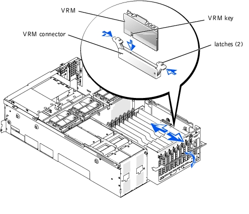
- Align the VRM's edge connector with the alignment key, and insert the VRM in the
connector (see Figure 4-23).
The VRM connector has an alignment key that allows the VRM to be installed in the socket in only one way.
- Press down on the VRM with your thumbs while pulling up on the ejectors with your
index fingers to lock the VRM into the connector (see Figure 4-23).
|
|
CAUTION: See "Protecting Against Electrostatic Discharge" in the safety instructions in your System Information document. |
- Turn off the system, including any attached peripherals, and disconnect the system
from the electrical outlet.
- Identify the VRM connectors on the microprocessor board (see Figure 5-4).
- Press down and outward on the VRM connector ejectors until the VRM pops out of
the socket (see Figure 4-24).
- Install the microprocessor tray ("Removing the Microprocessor Tray").
Remember the following when installing microprocessor VRMs:
- A VRM must be installed for each installed microprocessor.
- All VRMs must be of the same type.
- VRMs installed in sockets 2–4 are compared with the VRM in socket 1.
- If VRMs are not installed or do not match, an error message will appear on the front panel status LCD display (see "Indicators, Codes, and Error Messages").
|
|
CAUTION: See "Protecting Against Electrostatic Discharge" in the safety instructions in your System Information document. |
- Before you perform this procedure, you must turn off the system and disconnect it
from its power source.
- Remove the microprocessor tray (see "Removing the Microprocessor Tray").
- Place the microprocessor tray on a flat surface.
- Identify the VRM connectors on the microprocessor board (see Figure 5-4).
- Press down and outward on the VRM ejectors, as shown in Figure 4-24, to allow the
VRM to be inserted into the connector.
Figure 4-24. Installing the Microprocessor VRM
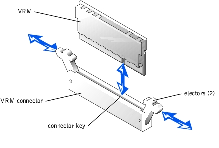
- Align the VRM's edge connector with the alignment key, and insert the VRM in the
connector (see Figure 4-24).
The VRM connector has an alignment key that allows the VRM to be installed in the socket in only one way.
- Press down on the VRM with your thumbs while pulling up on the ejectors with your
index fingers to lock the VRM into the connector (see Figure 4-24).
- Repeat steps 4 through 6 of this procedure to install the remaining VRMs.
To take advantage of future options in speed and functionality, you can add additional microprocessors or replace installed microprocessors.
|
NOTICE: The additional microprocessors must be of the same type and speed as the primary
microprocessor. All microprocessors must also have the same L2 and L3 cache sizes.
|
Each microprocessor and its associated cache memory are contained in a PGA package that is installed in a ZIF socket on the microprocessor board.
|
NOTE: Both a microprocessor and a VRM must be installed in the CPU1 and VRM1
sockets, respectively. To identify CPU1 and VRM1 sockets, see Figure 5-4.
|
|
NOTICE: If a microprocessor socket does not have a microprocessor installed, a heat sink
blank must be installed for that socket.
|
The following items are included in the microprocessor upgrade kit:
- A microprocessor
- A heat sink
- A VRM, if adding a second microprocessor
|
|
CAUTION: See "Protecting Against Electrostatic Discharge" in the safety instructions in your System Information document. |
- Turn off the system, including any attached peripherals, and disconnect the system
from the electrical outlet.
- Remove the microprocessor tray (see "Removing the Microprocessor Tray").
- Place the microprocessor tray on a flat surface.
- While holding the side-release lever tab, rotate the lever up until the microprocessor
cover front lever is released from the enclosure (see Figure 4-25).
Figure 4-25. Removing and Replacing the Microprocessor Cover
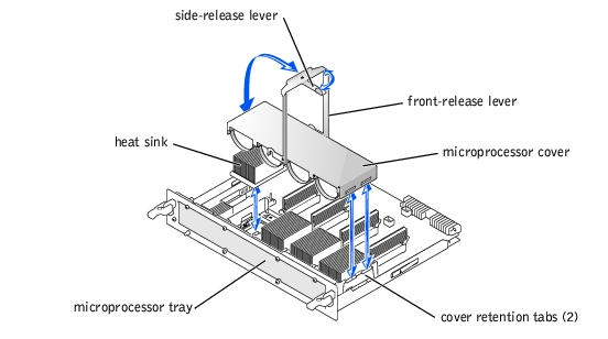
- While holding the front release lever, rotate the lever up until the cover is released
from the front of the enclosure (see Figure 4-25).
- Remove the microprocessor cover.
|
|
CAUTION: The microprocessor and heat sink can become extremely hot. Be sure the microprocessor has had sufficient time to cool before handling. |
|
NOTICE: Never remove the heat sink from a microprocessor unless you intend to remove the
microprocessor. The heat sink is necessary to maintain proper thermal conditions.
|
|
NOTICE: After removing the heat sink, it should be placed upside down on a flat surface to
prevent the thermal interface material from being damaged or contaminated.
|
- Remove the heat sink (see Figure 4-25).
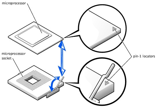
- Pull the socket release lever straight up until the microprocessor is released (see
Figure 4-26).
Figure 4-26. Removing and Replacing the Microprocessor
|
NOTICE: Be careful not to bend any of the pins when removing the microprocessor. Bending
the pins can permanently damage the microprocessor.
|
- Lift the microprocessor out of the socket and leave the release lever up so that the
socket is ready for the new microprocessor (see Figure 4-26).
- Unpack the new microprocessor.
If any of the pins on the microprocessor appear bent, see "Obtaining Technical Assistance."
- If the release lever on the microprocessor socket is not fully opened, move it to that
position now.
- Align the gold triangle on the microprocessor (see Figure 4-26) with the triangle on
the microprocessor socket.
|
NOTE: Zero insertion force is needed to install the microprocessor. If the microprocessor is
aligned correctly, it should drop into the microprocessor socket.
|
- Install the microprocessor in the socket (see Figure 4-26).
- When the microprocessor is fully seated in the socket, rotate the socket release lever
back down until it snaps into place, securing the microprocessor.
- Apply light pressure to the top of the microprocessor while rotating the socket release
lever down, securing the microprocessor.
- Place the new heat sink on top of the microprocessor (see Figure 4-25).
- Orient the microprocessor cover as shown in Figure 4-25.
|
NOTICE: Failure to properly install the microprocessor cover can permanently damage the
microprocessor(s). When installing the microprocessor cover, ensure that the cover retention
tabs on the edge of the microprocessor enclosure are inserted into the slots of the cover.
|
- Hook the end of the cover over the retention tabs on the edge of the microprocessor
enclosure (see Figure 4-25).
- Swing the microprocessor cover down.
- Rotate the side release lever down to secure the cover to the side of the microprocessor
enclosure (see Figure 4-25).
- Rotate the front release lever down to secure the cover to the front of the
microprocessor enclosure (see Figure 4-25).
- If you are adding additional microprocessors, install the VRM in the corresponding
VRM socket, pushing down firmly to make sure that the ejectors engage (see
"Replacing a Microprocessor VRM").
- Replace the microprocessor tray (see "Replacing the Microprocessor Tray").
- Reconnect your system and peripherals to their electrical outlets, and turn on the
system.
As the system boots, it detects the presence of the new microprocessor(s) and automatically changes the system configuration information in the System Setup program and displays the microprocessor ID number, operating speed, processor bus, and cache information.
- Press <F2> to enter the System Setup program, and check that the microprocessor
categories match the new system configuration (see "Using the System Setup
Program").
- Run the system diagnostics to verify that the new microprocessor is operating
correctly.
See "Running the System Diagnostics" for information on running the diagnostics and troubleshooting any problems that may occur.
|
|
CAUTION: Read the safety instructions in your System Information document. |
- Remove the microprocessor tray (see "Removing the Microprocessor Tray").
- Remove the Microprocessors (see "Adding or Replacing a Microprocessor").
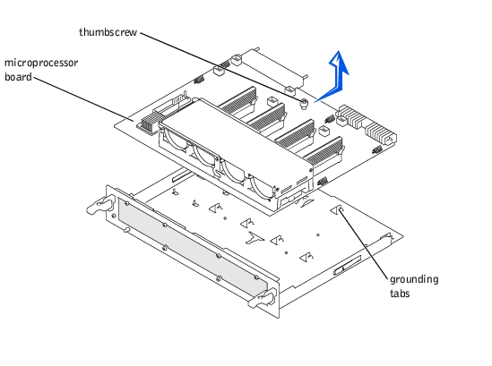
- Loosen the thumbscrew securing the microprocessor board.
- Slide the microprocessor board about 0.5 inch toward the back of the microprocessor
tray.
- Lift the microprocessor board up, away from the tray (see Figure 4-27).
Figure 4-27. Removing the Microprocessor Board
|
|
CAUTION: Read the safety instructions in your System Information document. |
- Align the microprocessor board with the grounding tabs on the microprocessor tray.
- Slide the board forward about 0.5 inch and tighten the thumbscrew that secures the
board to the microprocessor tray.
- Replace the heat sinks, microprocessors, and VRMs (see "Adding or Replacing a
Microprocessor").
- Replace the microprocessor tray (see "Replacing the Microprocessor Tray").
|
|
CAUTION: Read the safety instructions in your System Information document. |
- Turn off the system, including any attached peripherals, and disconnect the system
from the electrical outlet.
- Remove the microprocessor tray (see "Removing the Microprocessor Tray").
- Remove both power supplies.
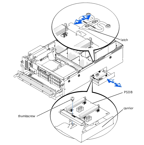
- Release the latch on the bottom of the power supply slots, while.sliding the PSDB and
its carrier out the side of the chassis.
- Loosen the thumbscrew that secures the PSDB to the chassis (see Figure 4-28).
- Slide the PSDB forward about 0.25 inch, lift the PSDB away, off its grounding tabs,
and off of the carrier (see Figure 4-28).
Figure 4-28. Removing the PSDB
|
|
CAUTION: Read the safety instructions in your System Information document. |
- Align the replacement PSDB with the grounding tabs on the carrier.
- Slide the PSDB backward about 0.25 inch.
- Tighten the thumbscrew that secures the PSDB to the chassis (see Figure 4-28).
- Slide the PSDB and its carrier into its slot on the side of the system chassis.
The latch clicks when the carrier is fully seated in its slot.
- Replace the power supplies (see "Replacing a Power Supply").
- Replace the microprocessor tray (see "Removing the Microprocessor Tray").
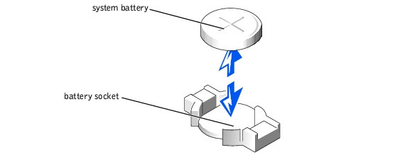
The system battery is a 3.0-volt (V), coin-cell battery. To replace the battery, perform the following steps.
|
|
CAUTION: Read the safety instructions in your System Information document. |
|
|
CAUTION: There is a danger of a new battery exploding if it is incorrectly installed. Replace the battery only with the same or equivalent type recommended by the manufacturer. Discard used batteries according to the manufacturer's instructions. |
- Enter the System Setup program and, if possible, make a printed copy of the System
Setup screens (see "Using the System Setup Program").
- Turn off the system, including any attached peripherals, and disconnect the system
from the electrical outlet.
|
|
CAUTION: See "Protecting Against Electrostatic Discharge" in the safety instructions in your System Information document. |
- Remove the back cover (see "Removing the Back Cover").
- Remove the I/O riser card (see "Removing the I/O Riser Card").
- Remove the system battery (see Figure 5-2).
You can pry the system battery out of its socket with your fingers or with a blunt, nonconductive object such as a plastic screwdriver.
- Install the new system battery with the side labeled "+" facing up (see Figure 4-29).
Figure 4-29. Installing the System Battery
- Replace the I/O riser card (see "Replacing the I/O Riser Card").
- Replace the back cover (see "Replacing the Back Cover").
- Reconnect the system and any attached peripherals to their electrical outlets and turn
them on.
- Enter the System Setup program to confirm that the battery is operating properly (see
"Using the System Setup Program").
- Enter the correct time and date in the System Setup program's Time and Date
settings.
- Re-enter any system configuration information that is no longer displayed on the
System Setup screens, and then exit the System Setup program.
- To test the newly installed battery, power down and disconnect the system from its
electrical source for at least an hour.
- After an hour, connect the system to its electrical source and turn on the system.
- Enter the System Setup program and if the time and date are still incorrect, see
"Obtaining Technical Assistance."
Back to Contents Page
 SCSI Configuration Information