Back to Contents Page
Service-Only Parts Replacement Procedures
Dell™ PowerEdge™ 800 Systems Installation and Troubleshooting Guide
 Recommended Tools
Control Panel Assembly
Chassis-Intrusion Switch
System Board
Recommended Tools
You may need the following items to perform the procedures in this section:
- Key to the system keylock
- Wrist grounding strap
- #2 Phillips screwdriver
Control Panel Assembly
Removing the Control Panel Assembly

|
CAUTION: See your Product Information Guide for complete information about safety precautions, working inside the computer, and protecting against electrostatic discharge. |
- Turn off the system and attached peripherals, and disconnect the system from the electrical
outlet.
- Remove the bezel. See "Removing the Bezel" in "Troubleshooting Your System."
- Lay the system on its right side.
- Remove the cover. See "Removing the Cover" in "Troubleshooting Your System."
- Disconnect the control panel assembly cable from the FRONT_PANEL connector on the
system board. See Figure A-3.
- Using a #2 Phillips screwdriver, remove the two mounting screws that secure the control
panel assembly to the chassis. See Figure C-1.
- Lift the control panel assembly and its cable away from the system. See Figure C-1.
Figure C-1. Removing the Control Panel Assembly
Installing the Control Panel Assembly
- Insert the control panel cable through the front of the system and connect the cable
connector to the FRONT_PANEL connector on the system board.
- Using a #2 Phillips screwdriver, install the screws that secure the control panel assembly to
the chassis. See Figure C-1.
- Close the system. See "Replacing the Cover" in "Troubleshooting Your System."
- Lift the system upright.
- Reinstall the bezel. See "Installing the Bezel" in "Troubleshooting Your System."
- Reconnect the system to its electrical outlet and turn the system on, including any attached
peripherals.
Chassis-Intrusion Switch
Removing the Chassis-Intrusion Switch
|
|
CAUTION: See your Product Information Guide for complete information about safety precautions, working inside the computer, and protecting against electrostatic discharge. |
- Turn off the system and attached peripherals, and disconnect the system from the electrical
outlet.
- Remove the bezel. See "Removing the Bezel" in "Troubleshooting Your System."
- Lay the system on its right side.
- Remove the cover. See "Removing the Cover" in "Troubleshooting Your System."
- Disconnect the fan power cable from the FRONT_FAN connector on the system board. See
Figure C-2.
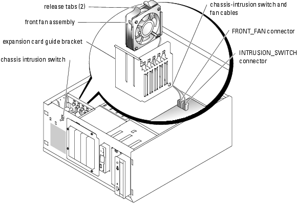
Figure C-2. Removing the Chassis-Intrusion Switch
- Compress the two release tabs on the top of the front fan assembly and lift the fan assembly
away from the system. See Figure C-2.
- Disconnect the chassis-intrusion switch cable from the INTRUSION_SWITCH connector
on the system board. See Figure C-2.
- Slide the chassis-intrusion switch upward out of its slot in the front panel, and guide the
switch cable through the expansion-card guide bracket and front panel.
Replacing the Chassis-Intrusion Switch
- Thread the chassis-intrusion switch cable through the holes in the front panel and
expansion-card guide bracket.
- Connect the chassis-intrusion switch cable to the INTRUSION_SWITCH connector on the
system board. See Figure C-2.
- Insert the end of the fan cable into the routing hole in the expansion-card guide bracket.
- Reinstall the front fan assembly.
Note the orientation of the fan assembly when installing it in the chassis. When the fan assembly is installed correctly, the fan faces toward the back of the system and the blue plastic grill faces toward the front of the system. See Figure C-2.
- Pull the fan cable through the routing hole in the expansion-card guide bracket.
- Connect the fan cable to the FRONT_FAN connector on the system board. See Figure C-2.
- Close the system. See "Replacing the Cover" in "Troubleshooting Your System."
- Lift the system upright.
- Reinstall the bezel. See "Installing the Bezel" in "Troubleshooting Your System."
System Board
The system board and system board tray are removed and replaced as a single assembly.
|
|
CAUTION: See your Product Information Guide for complete information about safety precautions, working inside the computer, and protecting against electrostatic discharge. |
|
|
CAUTION: The processor heat sink can get hot during operation. To avoid burns, ensure that the system has sufficient time to cool before removing the system board. |
Removing the System Board
- Turn off the system and attached peripherals, and disconnect the system from the electrical
outlet.
- Disconnect the cables to the I/O connectors on the back panel.
- Remove the bezel. See "Removing the Bezel" in "Troubleshooting Your System."
- Lay the system on its right side.
- Remove the cover. See "Removing the Cover" in "Troubleshooting Your System."
- Disconnect the two power cables from connectors PWR_CONN and 12V on the system
board.
- Remove the cooling shroud. See "Removing the Cooling Shroud" in "Installing System
Components."
- If the system has cabled SCSI drives or SATA drives, note the relative location of the interface
cable connections between the system board and the drives, so you can reconnect them in the
proper sequence.
- Disconnect the SCSI or SATA interface cable(s) connected to the system board or optional
hard-drive controller card.
- Disconnect the power cable(s) connected to the hard drives in the drive cage, or to the
optional SCSI backplane.
- Remove the screws securing the drive cage and remove the cage from the system. See
Figure 7-6 in "Installing Drives."
- Disconnect all remaining cables attached to the connectors on the system board:
- Optical-drive interface cable (PRIMARY_IDE connector)
- Diskette-drive cable (FDD connector)
- Control panel cable (FRONT_PANEL connector)
- Chassis-intrusion switch cable (INTRUSION_SWITCH connector)
- Front fan cable (FRONT_FAN connector)
- Back fan cable (BACK_FAN connector)
- Any other cables attached to the system board, after recording their locations.
- Remove the back fan. See "Removing the Back System Fan" in "Installing System
Components."
- Remove all PCI expansion cards from the expansion slots. See "Removing an Expansion Card"
in "Installing System Components."
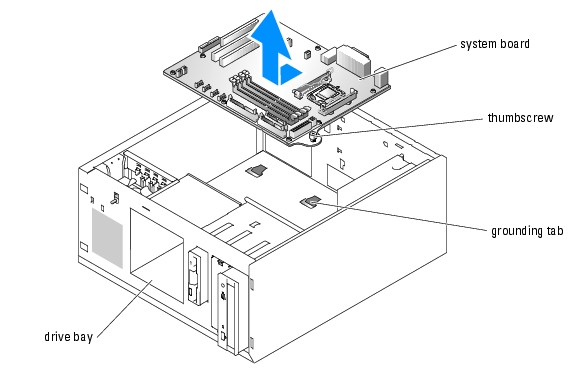
- Loosen the thumbscrew that secures the system board tray to the chassis. See Figure C-3.
- Slide the system board toward the front of the chassis about 2.5 cm (1 inch).
- Carefully lift the system board up and out of the chassis. See Figure C-3.
Figure C-3. Removing the System Board
Installing the System Board
- Unpack the new system board.
- Ensure that the system board jumpers are set the same as on the board that you just removed,
and change the settings if necessary. See Figure A-2 in "Jumpers, Switches, and Connectors."
- Remove the memory modules from the original system board and transfer them to the new
board, being careful to install the memory modules in the same locations.
See "Removing Memory Modules" and "Installing Memory Modules" in "Installing System Components."
- Remove the processor from the original system board. See "Removing the Processor" in
"Installing System Components."
- Reinstall the processor and heat sink on the new system board. See "Installing a Processor" in
"Installing System Components."
- Making sure that no cables are trapped beneath the system board tray, lower the new system
board into the chassis.
- Slide the system board toward the back of the chassis as far as it will go.
- Tighten the thumbscrew that secures the system board tray to the chassis.
- Install the back fan and connect the fan cable to the BACK_FAN connector on the system
board. See "Installing the Back System Fan" in "Installing System Components."
- Connect the following cables to the system board. See Figure A-3.
- Optical-drive interface cable (PRIMARY_IDE connector)
- Diskette-drive cable (FDD connector)
- Control panel cable (FRONT_PANEL connector)
- Chassis-intrusion switch cable (INTRUSION_SWITCH connector)
- Front fan cable (FRONT_FAN connector)
- Install all expansion cards and connect any interface cables to the appropriate components in
the system. See "Installing an Expansion Card" in "Installing System Components."
- Reinstall the drive cage and secure it with the four Phillips screws. See Figure 7-6 in
"Installing Drives."
- Reconnect the SCSI or SATA interface cable(s) to the system board or optional hard-drive
controller card.
Ensure that you reattach the interface cables in their original locations.
- Reconnect the power cables to the hard drives in the drive cage, or to the optional SCSI
backplane.
- Replace the cooling shroud. See "Installing the Cooling Shroud" in "Installing System
Options."
- Connect the two power cables to connectors PWR_CONN and 12V on the system board.
- Carefully check for any remaining cables or components that are not installed or are
improperly seated in their connectors on the system board.
- Close the system. See "Replacing the Cover" in "Troubleshooting Your System."
- Lift the system upright.
- Reinstall the bezel. See "Installing the Bezel" in "Troubleshooting Your System."
- Reconnect the cables to the I/O connectors on the system back panel.
- Reconnect the system to its electrical outlet and turn the system on, including any attached
peripherals.
Back to Contents Page