Other Information You May Need
Dell™ PowerEdge™ 840 Systems Hardware Owner's Manual
Other Information You May Need
Accessing System Features During Startup
Front-Panel Features and Indicators
Back-Panel Features and Indicators
Baseboard Management Controller Messages
This section describes the physical, firmware, and software interface features that provide and ensure the essential functioning of your system. The physical connectors on your system's front and back panels provide convenient connectivity and system expansion capability. The system firmware, applications, and operating systems monitor the system and component status and alert you when a problem arises. System conditions can be reported by any of the following:
This section describes each type of message, lists the possible causes, and provides steps to resolve any problems indicated by a message. The system indicators and features are illustrated in this section.

|
CAUTION: The Product Information Guide provides important safety and regulatory information. Warranty information may be included within this document or as a separate document. |

|
NOTE: Always check for updates on support.dell.com and read the updates first because they often supersede information in other documents. |
Table 1-1 describes keystrokes that may be entered during startup to access system features. If your operating system begins to load before you enter the keystroke, allow the system to finish booting, and then restart your system and try again.
Table 1-1. Keystrokes for Accessing System Features
|
Keystroke |
Description |
|---|---|
<F2> | Enters the System Setup program. See Using the System Setup Program. |
<F10> | Opens the utility partition, allowing you to run the system diagnostics. See Running the System Diagnostics. |
<Ctrl+E> | Enters the Baseboard Management Controller (BMC) Management Utility, which allows access to the system event log (SEL). See the BMC User's Guide for more information on setup and use of BMC. |
<Ctrl+C> | Enters the SAS Configuration Utility. See your SAS adapter User's Guide for more information. |
<Ctrl+R> | Enters the RAID configuration utility, which allows you to configure an optional RAID card. For more information, see the documentation for your RAID card. |
<Ctrl+S> | Option is displayed only if you have PXE support enabled through the System Setup Program (see Integrated Devices Screen). This keystroke allows you to configure NIC settings for PXE boot. For more information, see the documentation for your integrated NIC. |
<Ctrl+D> | If you have the optional Dell Remote Access Controller (DRAC), this keystroke allows access to selected DRAC configuration settings. See the DRAC User's Guide for more information on setup and use of DRAC. |
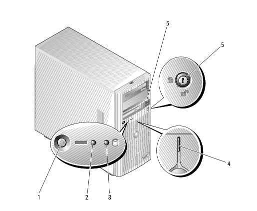
Figure 1-1 shows the controls, indicators, and connectors located on the system's front panel. Table 1-2 provides component descriptions.
Figure 1-1. Front-Panel Features and Indicators
|
1 |
power button |
2 |
power-on indicator |
3 |
hard-drive activity indicator |
|
4 |
system status indicator |
5 |
security lock |
6 |
USB connectors (2) |
Table 1-2. Front-Panel Components
|
Item |
Component |
Icon |
Description |
|---|---|---|---|
1 | Power button |
| The power button turns system power off and on. NOTICE: If you turn off the system using the power button and the system is running an ACPI-compliant operating system, the system can perform an orderly shutdown before power is turned off. If the power button is pressed for more than 4 seconds, the system power will turn off regardless of the current operating system state. If the system is not running an ACPI-compliant operating system, power is turned off immediately after the power button is pressed. The power button is enabled in the System Setup program. When disabled, the button can only turn the system power on. For more information, see Using the System Setup Program and the operating system's documentation. |
2 | Power-on indicator |
| On: System power is on. Blinking: System is on but in standby state, or system is off but still connected to the power source. |
3 | Hard-drive activity indicator |
| Flashes when data is being read from or written to the internal SATA hard drives that are connected to the integrated controller. |
4 | System status indicator |
| Blue: Normal system operation. Amber: Flashes when the system needs attention due to a problem with power supplies, fans, system temperature, or hot-plug hard drives. NOTE: If the system is connected to AC power and an error has been detected, the amber system status indicator flashes regardless of whether the system has been powered on. |
5 | Security lock |
| Controls access to the system's internal components.
|
6 | USB connectors |
| Connects USB 2.0-compliant devices to the system.
|
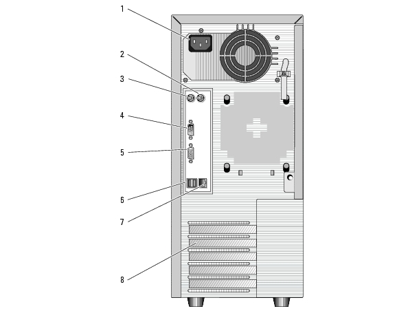
Figure 1-2 shows the connectors located on the system's back panel.
Figure 1-2. Back-Panel Features
|
1 |
AC power connector |
2 |
mouse connector |
3 |
keyboard connector |
|
4 |
serial connectors (5) |
5 |
video connector |
6 |
USB connector (2) |
|
7 |
NIC connector |
8 |
expansion slots (5) |
|
|
When connecting external devices to your system, follow these guidelines:
See Using the System Setup Program for information about enabling, disabling, and configuring I/O ports and connectors.
The NIC on the back panel has an indicator that provides information on network activity and link status. See Figure 1-3. Table 1-3 lists the NIC indicator codes.

|
1 |
link indicator |
2 |
activity indicator |
|
|
Table 1-3. NIC Indicator Codes
|
Indicator Type |
Indicator Code |
Description |
|---|---|---|
Activity | Off | When off at the same time that the link indicator is off, the NIC is not connected to the network or the NIC is disabled in the System Setup program. See Using the System Setup Program. |
Blinking yellow | Indicates that network data is being sent or received. | |
Link | Off | When off at the same time that the activity indicator is off, the NIC is not connected to the network or the NIC is disabled in the System Setup program. See Using the System Setup Program. |
On (green) | Indicates active link. |
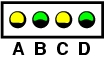
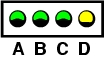
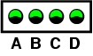
Four diagnostic indicator lights are located behind the bezel on the I/O control panel. To access the lights, see Opening the System. These lights display error codes during system startup. Table 1-4 lists the causes and corrective actions associated with these codes and the power light status before system POST. Table 1-6 lists the causes and possible corrective actions for these codes during POST. A highlighted circle indicates the light is on; a non-highlighted circle indicates the light is off.
Table 1-4. Diagnostic Indicator Codes
|
Code |
Causes |
Corrective Action |
|---|---|---|
|
| No power is applied to the system.
| |
|
| A possible processor failure has occurred.
| |
|
| Memory failure. | |
|
| Possible expansion-card failure.
| |
|
| Possible video card failure. | |
|
| Diskette or hard-drive failure. | Ensure that the diskette drive and hard drive(s) are properly connected. See Hard Drives for information on the drive(s) installed in your system. |
|
| Possible USB failure. | |
|
| No memory modules detected. | |
|
| System board failure. | See Getting Help." |
|
| Memory configuration error. | |
|
| Possible system board resource and/or system board hardware failure. | See Getting Help." |
|
| Possible expansion card failure. | |
|
| Other failure. | Ensure that the diskette drive, optical drive, and hard drive(s) are properly connected. See Troubleshooting Your System" for the appropriate drive(s) installed in your system. If the problem persists, see Getting Help." |
|
| The system is in a normal operating condition after POST. | Information only. |
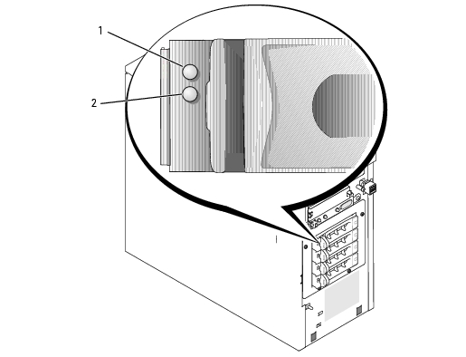
If an optional SAS backplane is installed in the system, two indicators on each of the hard-drive carriers provide information on the status of the hard drives. See Figure 1-4 and Table 1-5. The SAS backplane firmware controls the drive power-on/fault indicator.
Figure 1-4. Hard-Drive Indicators
|
1 |
drive status indicator |
2 |
drive busy indicator |
|
|
Table 1-5 lists the drive indicator patterns. Different patterns are displayed as drive events occur in the system. For example, if a hard drive fails, the "drive failed" pattern appears. After the drive is selected for removal, the "drive being prepared for removal" pattern appears, followed by the "drive ready for insertion or removal" pattern. After the replacement drive is installed, the "drive being prepared for operation" pattern appears, followed by the "drive online" pattern.
|
|
NOTE: If a RAID controller is not installed, only the "drive online" indicator pattern appears. The drive-activity indicator also blinks when the drive is being accessed. |
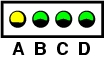
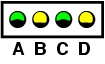
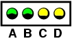
Table 1-5. Drive Indicator Patterns
System messages appear on the screen to notify you of a possible problem with the system. Table 1-6 lists the system messages that can occur and the probable cause and corrective action for each message.
|
|
NOTE: If you receive a system message that is not listed in Table 1-6, check the documentation for the application that is running when the message appears or the operating system's documentation for an explanation of the message and recommended action. |
|
Message |
Causes |
Corrective Actions |
|---|---|---|
|
Amount of available memory limited to 256MB | OS Install Mode is enabled in the System Setup program. | Disable OS Install Mode in the System Setup program. See Using the System Setup Program. |
|
Attempting to update Remote Configuration. Please wait.... | Remote Configuration is in progress. | Wait until the process is complete. |
|
BIOS Update Attempt Failed | BIOS remote update failed. | Retry update. |
|
Caution! NVRAM_CLR jumper is installed on system board. | NVRAM_CLR jumper is installed. | Remove the NVRAM_CLR jumper. See System Board Jumpers for the jumper location. |
|
Data error | Faulty diskette, diskette drive, optical drive, hard drive. | Replace the diskette. Ensure that the diskette drive, optical drive, and hard- drive cables are properly connected. See Troubleshooting a Diskette Drive or Troubleshooting an Optical Drive for the appropriate drive(s) installed in your system. |
|
Decreasing available memory | Faulty or improperly installed memory modules. | Ensure that all memory modules are properly installed. See "Troubleshooting System Memory. |
|
Diskette drive 0 seek failure | Incorrect configuration settings in System Setup program. | Run the System Setup program to correct the settings. See Using the System Setup Program. |
Faulty or improperly installed diskette, loose diskette drive or optical drive interface cable, or loose power cable. | Replace the diskette. Ensure that the diskette drive and optical drive cables are properly connected. See "Troubleshooting a Diskette Drive" and "Troubleshooting an Optical Drive" in "Troubleshooting Your System." | |
|
Diskette read failure | Faulty or improperly inserted diskette. | Replace the diskette. |
|
Diskette subsystem reset failed | Faulty diskette drive or optical drive controller. | Ensure that the diskette drive and optical drive cables are properly connected. See Troubleshooting a Diskette Drive and Troubleshooting an Optical Drive. If the problem persists, see Getting Help. |
|
Drive not ready | Diskette missing or improperly inserted in diskette drive. | Reinsert or replace the diskette. |
|
Error: Incorrect memory configuration. Ensure memory in slots DIMM1_A and DIMM1_B, DIMM2_A and DIMM2_B match identically in size, speed, and rank. | An unmatched pair of memory modules is installed. | Install a matched pair of memory modules, or remove the memory module in socket DIMM1_B. See General Memory Module Installation Guidelines. |
|
Error: Remote Access Card initialization failure. | Faulty or improperly installed RAC. | Ensure that the RAC is properly installed. See Troubleshooting Expansion Cards. |
|
Error 8602: Auxiliary device failure. Verify that the mouse and keyboard are securely attached to correct connectors. | Loose or improperly connected mouse or keyboard cable; faulty mouse or keyboard. | Replace the mouse. If the problem persists, replace the keyboard. |
|
Gate A20 failure | Faulty keyboard controller (faulty system board). | See Getting Help. |
|
General failure | Operating system corrupted or improperly installed. | Reinstall the operating system. |
|
IDE Primary drive x not found | Improperly connected or missing optical drive or tape backup unit. | Ensure that the drive cables are properly connected. See Troubleshooting Your System for the appropriate drive installed in your system. If no drive is installed, disable the IDE controller. See Using the System Setup Program. |
|
Invalid memory configuration detected. Potential for data corruption exists! | Unsupported DIMMs are installed in the system, or the memory configuration is incorrect. | Replace or reconfigure the DIMMs. See Memory for memory configuration guidelines, a list of supported DIMMs, and supported memory configurations. |
|
Keyboard controller failure | Faulty keyboard controller (faulty system board). | See Getting Help. |
|
Keyboard data line failure Keyboard failure Keyboard stuck key failure | Loose or improperly connected keyboard cable; faulty keyboard; faulty keyboard controller. | Ensure that the keyboard is properly connected. If the problem persists, replace the keyboard. If the problem persists, see Getting Help. |
|
Keyboard fuse has failed. | Keyboard fuse has failed. | Replace the keyboard. |
|
Manufacturing mode detected | System is incorrectly configured. | Install the NVRAM_CLR jumper and reboot the system. See System Board Jumpers for jumper location. |
|
Memory address line failure at address, read value expecting value Memory double word logic failure at address, read value expecting value Memory odd/even logic failure at address, read value expecting value Memory write/read failure at address, read value expecting value | Faulty or improperly installed memory modules, or faulty system board. | Ensure that all memory modules are properly installed. See Troubleshooting System Memory. If the problem persists, see Getting Help. |
|
Memory tests terminated by keystroke
| The spacebar was pressed during POST to terminate the memory test.
| Information only.
|
|
More than one RAC detected, system halted |
| Verify that the RAC is installed in the proper PCI expansion slot (SLOT_5). If a RAC is installed in any other slot, remove it. |
|
No boot device available | Faulty or missing diskette drive, optical drive, or hard drive.
| Check the Integrated Devices configuration settings in the System Setup program. See Using the System Setup Program. Ensure that either SATA Controller, Diskette Controller, or IDE Controller is enabled. If the system is booting from a SCSI controller, ensure that the controller is properly connected. If the problem persists, replace the drive. See Hard Drives. |
|
No boot sector on hard-disk drive | An operating system is not on the hard drive. | Check the hard-drive configuration settings in the System Setup program. See Using the System Setup Program. |
|
No timer tick interrupt | Faulty system board. | See Getting Help. |
|
Not a boot diskette | Not a bootable diskette. | Use a bootable diskette. |
|
PCI BIOS failed to install | Loose cables to expansion card(s); faulty or improperly installed expansion card. | Ensure that all appropriate cables are securely connected to the expansion cards. See Troubleshooting Expansion Cards. |
|
PCIe Degraded Link Width Error: Expected Link Width is n Actual Link Width is n | Faulty or improperly installed PCIe card. | Reseat the PCIe cards. See Expansion Cards. If the problem persists, see Getting Help. |
|
PCIe Degraded Link Width Error: Slot n Expected Link Width is n Actual Link Width is n | Faulty or improperly installed PCIe card in the specified slot number. | Reseat the PCIe card in the specified slot number. See Expansion Cards. If the problem persists, see Getting Help. |
|
PCIe Training Error: Embedded Bus#nn/Dev#nn/Funcn | Faulty or improperly installed PCIe card. | Reseat the PCIe cards. See Expansion Cards. If the problem persists, see Getting Help. |
|
PCIe Training Error: Slot n | Faulty or improperly installed PCIe card in the specified slot number. | Reseat the PCIe card in the specified slot number. See Expansion Cards. If the problem persists, see Getting Help. |
|
Plug & Play Configuration Error | Error encountered in initializing PCI device; faulty system board. | Install the NVRAM_CLR jumper and reboot the system. See Figure 6-1 for jumper location. Check for a BIOS update. If the problem persists, see Troubleshooting Expansion Cards. If the problem persists, see Getting Help. |
|
Primary drive n configuration error Primary drive 1 failure | Faulty hard-disk drive. | Replace the hard-disk drive. See Troubleshooting SATA Hard Drives or Troubleshooting a SAS RAID Controller in for the appropriate drive(s) installed in your system. |
|
Read fault | Faulty diskette, diskette drive, optical drive, or hard drive. | Replace the diskette. Ensure that the diskette, optical, and hard-drive cables are properly connected. See Troubleshooting a Diskette Drive, Troubleshooting an Optical Drive, Troubleshooting SATA Hard Drives," or Troubleshooting a SAS RAID Controller" for the appropriate drive(s) installed in your system. |
|
Remote Configuration update attempt failed | System could not implement Remote Configuration request. | Retry Remote Configuration. |
|
ROM bad checksum = address | Faulty or improperly installed expansion card. | Remove and reseat the expansion cards. See Troubleshooting Expansion Cards. |
|
SATA Port n hard disk drive configuration error SATA Port n hard disk drive failure SATA Port n hard disk drive auto-sensing error | Faulty SATA hard drive. | Replace the hard-disk drive. See Troubleshooting SATA Hard Drives for the appropriate drive(s) installed in your system. |
|
SATA Port n hard disk not found | SATA hard drive not connected to port n. | Ensure that the hard-drive cable is properly connected. See Hard Drives. If a drive is not connected to port n, check that the SATA port is disabled in the System Setup program. See Using the System Setup Program. |
|
Sector not found Seek error Seek operation failed | Faulty diskette or hard drive. | Replace the diskette. If the problem persists, see Troubleshooting SATA Hard Drives or Troubleshooting a SAS RAID Controller for the appropriate drive installed in your system. |
|
Shutdown failure | Shutdown test failure. | Ensure that all memory modules are properly installed. See Troubleshooting System Memory. If the problem persists, see Getting Help. |
|
The amount of system memory has changed. | Faulty memory module. | See Troubleshooting System Memory. If the problem persists, see Getting Help. |
|
The amount of tested memory is below the minimum system configuration. System halted! | Invalid memory configuration | |
|
| Faulty memory module. | See Troubleshooting System Memory. If the problem persists, see Getting Help." |
|
Time-of-day clock stopped | Faulty battery; faulty system board. | See Troubleshooting the System Battery. If the problem persists, see Getting Help. |
|
Time-of-day not set - please run SETUP program | Incorrect Time or Date settings; faulty system battery. | Check the Time and Date settings See "Using the System Setup Program" in your User's Guide. If the problem persists, see Troubleshooting the System Battery. |
|
Timer chip counter 2 failed | Faulty system board. | See Getting Help. |
|
Unexpected interrupt in protected mode | Faulty or improperly installed memory modules or faulty system board. | Ensure that all memory modules are properly installed. See General Memory Module Installation Guidelines. If the problem persists, see Troubleshooting System Memory. If the problem persists, see Getting Help. |
|
Utility partition not available | <F10> key was pressed during POST, but no utility partition exists on the boot hard drive. | Create a utility partition on the boot hard drive. See the CDs that came with your system. |
|
Warning! No microcode update loaded for processor n | Unsupported processor. | Update the BIOS firmware using the Dell Support website at support.dell.com. |
|
Write fault Write fault on selected drive | Faulty diskette, diskette drive, optical drive, hard drive. | Replace the diskette. Ensure that the diskette drive, optical drive, and hard- drive cables are properly connected. See Troubleshooting a Diskette Drive, Troubleshooting an Optical Drive," or Troubleshooting a Hard Drive for the appropriate drive(s) installed in your system. |
If an error that cannot be reported on the screen occurs during POST, the system may emit a series of beeps that identifies the problem.
|
|
NOTE: If the system boots without a keyboard, mouse, or monitor attached, the system does not issue beep codes related to those peripherals. |
If a beep code is emitted, write down the series of beeps and then look it up in Table 1-7. If you are unable to resolve the problem by looking up the meaning of the beep code, use system diagnostics to identify the possible cause. If you are still unable to resolve the problem, see Getting Help.
|
Code |
Cause |
Corrective Action |
|---|---|---|
1-1-2 | CPU register test failure | |
1-1-3 | CMOS write/read failure; faulty system board | Faulty system board. See Getting Help. |
1-1-4 | BIOS error | Reflash the BIOS. |
1-2-1 | Programmable interval-timer failure; faulty system board | Faulty system board. See Getting Help. |
1-2-2 | DMA initialization failure | |
1-2-3 | DMA page register write/read failure | |
1-3-1 | Main-memory refresh verification failure | |
1-3-2 | No memory installed | |
1-3-3 | Chip or data line failure in the first 64 KB of main memory | |
1-3-4 | Odd/even logic failure in the first 64 KB of main memory | |
1-4-1 | Address line failure in the first 64 KB of main memory | |
1-4-2 | Parity failure in the first 64 KB of main memory | |
1-4-3 | Fail-safe timer test failure | |
1-4-4 | Software NMI port test failure | |
2-1-1 through | Bit failure in the first 64 KB of main memory | |
3-1-1 | Slave DMA-register failure | Faulty system board. See Getting Help. |
3-1-2 | Master DMA-register failure | |
3-1-3 | Master interrupt-mask register failure | |
3-1-4 | Slave interrupt-mask register failure | |
3-2-2 | Interrupt vector loading failure | |
3-2-4 | Keyboard-controller test failure | |
3-3-1 | CMOS failure | |
3-3-2 | System configuration check failure | |
3-3-3 | Keyboard controller not detected | |
3-3-4 | Video memory test failure | |
3-4-1 | Screen initialization failure | |
3-4-2 | Screen-retrace test failure | |
3-4-3 | Video ROM search failure | |
4-2-1 | No timer tick | Faulty system board. See Getting Help. |
4-2-2 | Shutdown test failure | |
4-2-3 | Gate A20 failure | |
4-2-4 | Unexpected interrupt in protected mode | |
4-3-1 | Improperly installed or faulty memory modules | |
4-3-2 | No memory modules installed in the first memory module connector | Install a memory module in the first memory module connector. See Memory. |
4-3-3 | Faulty system board | Faulty system board. See Getting Help. |
4-3-4 | Time-of-day clock stopped | See Troubleshooting System Memory. If the problem persists, see Getting Help. |
4-4-1 | Super I/O chip failure; faulty system board | Faulty system board. See Getting Help. |
4-4-4 | Cache test failure; faulty processor |
A warning message alerts you to a possible problem and prompts you to respond before the system continues a task. For example, before you format a diskette, a message will warn you that you may lose all data on the diskette. Warning messages usually interrupt the task and require you to respond by typing y (yes) or n (no).
|
|
NOTE: Warning messages are generated by either the application or the operating system. For more information, see the documentation that accompanied the operating system or application. |
When you run system diagnostics, an error message may result. Diagnostic error messages are not covered in this section. Record the message on a copy of the Diagnostics Checklist in "Getting Help," and then follow the instructions in that section for obtaining technical assistance.
Systems management software generates alert messages for your system. Alert messages include information, status, warning, and failure messages for drive, temperature, fan, and power conditions. For more information, see the systems management software documentation.
The Baseboard Management Controller (BMC) enables you to configure, monitor, and recover systems remotely. BMC uses the system's serial port and integrated NIC1 to support fault logging and SNMP alerting.
|
|
NOTE: If the integrated network controller is used in an Ether Channel team or link aggregation team, the BMC management traffic will not function properly. For more information about network teaming, see the documentation for the network controller. |
For additional information on using BMC, see the documentation for the BMC and systems management applications.