 Optical Drive
Dell™ PowerEdge™ 850 Systems Installation and Troubleshooting Guide
SCSI Configuration Information
Installing a SCSI Controller Card
Your system contains up to two SATA or SCSI hard drives and an optional optical drive. If your system contains SCSI hard drives, they must be connected to a optional SCSI controller card. The integrated SATA controller supports up to two SATA hard drives.
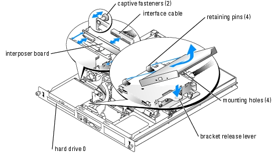
The optional optical drive is mounted in a bracket using two alignment pins and a spring clip on top of hard drive 0. An interposer card is connected to the back of the drive which allows the drive to be connected to the Pri-IDE connector on the system board.

|
CAUTION: Only trained service technicians are authorized to remove the system cover and access any of the components inside the system. Before performing any procedure, see your Product Information Guide for complete information about safety precautions, working inside the computer and protecting against electrostatic discharge. |
Figure 6-1. Removing and Installing the Optional Optical Drive
|
|
CAUTION: Only trained service technicians are authorized to remove the system cover and access any of the components inside the system. Before performing any procedure, see your Product Information Guide for complete information about safety precautions, working inside the computer and protecting against electrostatic discharge. |
Push the plungers into the captive fastener barrels until they snap into place.
Although SCSI drives are installed in essentially the same way as other drives, their configuration requirements are different. To install and configure a SCSI drive, follow the guidelines in the following subsections.
SCSI interface connectors are keyed for correct insertion. Keying ensures that the pin-1 wire in the cable connects to pin 1 in the connectors on both ends. When you disconnect an interface cable, take care to grasp the cable connector, rather than the cable itself, to avoid stress on the cable.
Each drive attached to a SCSI controller must have a unique SCSI ID number from 0 to 15.

|
NOTE: There is no requirement that SCSI ID numbers be assigned sequentially or that drives be attached to the cable in order by ID number. |
SCSI logic requires that termination be enabled for the two drives at opposite ends of the SCSI chain and disabled for all drives in between. For internal SCSI drives, termination is configured automatically. See the documentation provided with any optional SCSI drive you purchase for information on disabling termination.
The drive or device from which the system boots is determined by the boot order specified in the System Setup program. See "Using the System Setup Program" in your User's Guide. To boot the system from a hard drive or drive array, the drive(s) must be connected to the appropriate controller:
Your system contains up to two non-hot-pluggable SATA or SCSI hard drives. If your system contains SCSI hard drives, they must be connected to a SCSI controller card. The cables for hard drive 1 are routed through a cable clamp mounted to the chassis.
The procedures for removing and installing SATA or SCSI hard drives are the same.
|
|
CAUTION: Only trained service technicians are authorized to remove the system cover and access any of the components inside the system. Before performing any procedure, see your Product Information Guide for complete information about safety precautions, working inside the computer and protecting against electrostatic discharge. |
Remove the optical drive if you are removing hard drive 0. See "Removing the Optical Drive."
The interface cables for SATA hard drives are connected to the daughter card. See Figure A-3 for the location of the daughter card connectors.
The interface cables for SCSI hard drives are connected to a controller card.
Figure 6-2. Removing the Hard-Drive Carrier
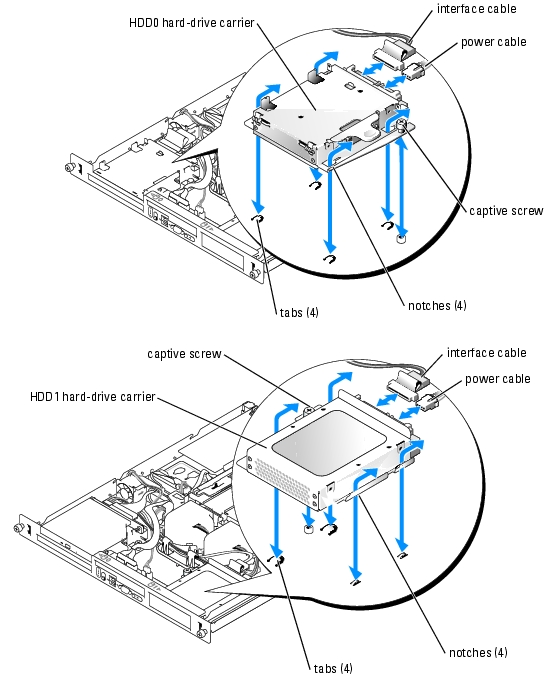
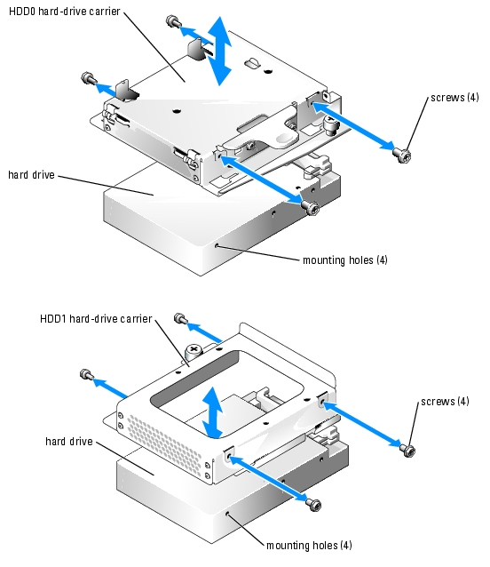
Figure 6-3. Removing the Hard Drives From the Drive Carriers
|
|
CAUTION: Only trained service technicians are authorized to remove the system cover and access any of the components inside the system. Before performing any procedure, see your Product Information Guide for complete information about safety precautions, working inside the computer and protecting against electrostatic discharge. |
The interface cables for SATA hard drives are connected to the daughter card. See Figure A-3 for the location of the daughter card connectors.
The interface cables for SCSI hard drives are connected to a SCSI controller card.
Install the CD drive if you are removing hard drive 0. See "Installing the Optical Drive."
See "Installing an Expansion Card" in "Installing System Components" for general instructions about installing the controller card. See the controller card documentation for specific information on installing and configuring the card.