Back to Contents Page
Service-Only Parts Replacement Procedures
Dell™ PowerEdge™ 850 Systems Installation and Troubleshooting Guide
 Recommended Tools
Control Panel Assembly
Daughter Card
System Board
Recommended Tools
You may need the following items to perform the procedures in this section:
- Key to the system keylock
- Wrist grounding strap
- #2 Phillips screwdriver
Control Panel Assembly
Removing the Control Panel Assembly

|
CAUTION: Only trained service technicians are authorized to remove the system cover and access any of the components inside the system. Before performing any procedure, see your Product Information Guide for complete information about safety precautions, working inside the computer and protecting against electrostatic discharge. |
- Open the system. See "Opening the System" in "Troubleshooting Your System."
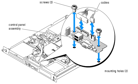
- Disconnect the control panel cables. See Figure 7-1.
- Using a #2 Phillips screwdriver, remove the two screws that secure the control panel assembly
to the chassis. See Figure 7-1.
- Carefully lift the back of the control panel assembly to clear the chassis mounting studs, and
remove the assembly from the system.
Figure 7-1. Removing the Control Panel Assembly
Installing the Control Panel Assembly
|
|
CAUTION: Only trained service technicians are authorized to remove the system cover and access any of the components inside the system. Before performing any procedure, see your Product Information Guide for complete information about safety precautions, working inside the computer and protecting against electrostatic discharge. |
- Align the control panel assembly's mounting holes with the chassis mounting holes. See
Figure 7-1.
- Using a #2 Phillips screwdriver, install the two screws that secure the control panel assembly
to the chassis. See Figure 7-1.
- Connect the control panel cables. See Figure 7-1.
- Close the system. See "Closing the System" in "Troubleshooting Your System."
Daughter Card
Removing the Daughter Card
|
|
CAUTION: Only trained service technicians are authorized to remove the system cover and access any of the components inside the system. Before performing any procedure, see your Product Information Guide for complete information about safety precautions, working inside the computer and protecting against electrostatic discharge. |
- Open the system. See "Opening the System" in "Troubleshooting Your System."
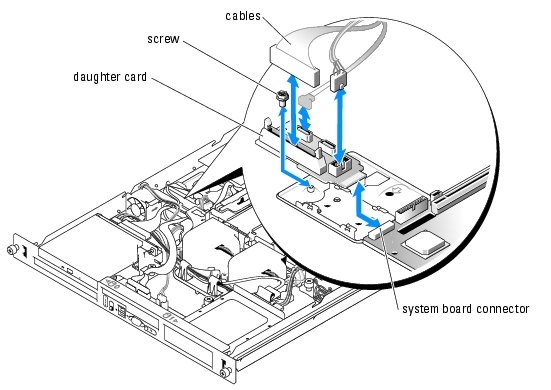
- Disconnect the SATA, control panel, and optical drive cables, and disconnect the PCI fan
cable if present. See Figure 7-2.
- Using a #2 Phillips screwdriver, remove the screw that secures the daughter card to the
chassis. See Figure 7-2.
- Slide the daughter card away from the connector on the edge of the system board and remove
it from the system.
Figure 7-2. Removing the Daughter Card
Installing the Daughter Card
|
|
CAUTION: Only trained service technicians are authorized to remove the system cover and access any of the components inside the system. Before performing any procedure, see your Product Information Guide for complete information about safety precautions, working inside the computer and protecting against electrostatic discharge. |
- Slide the daughter card into the connector on the edge of the system board. See Figure 7-2.
- Using a #2 Phillips screwdriver, install the screw that secures the daughter card to the chassis.
See Figure 7-2.
- Connect the optical drive, control panel, and SATA cables, and connect the PCI fan cable if
applicable. See Figure 7-2.
- Close the system. See "Closing the System" in "Troubleshooting Your System."
System Board
The system board provides interface signal routing between the system board and the two SATA hard-drive bays, the optional CD drive, and the control panel. In addition, the power supply is connected to the system board using two cables.
The system board and system board tray are removed and replaced as a single assembly.
Removing the System Board Assembly
|
|
CAUTION: Only trained service technicians are authorized to remove the system cover and access any of the components inside the system. Before performing any procedure, see your Product Information Guide for complete information about safety precautions, working inside the computer and protecting against electrostatic discharge. |
- Open the system. See "Opening the System" in "Troubleshooting Your System."
- Remove the cooling shroud. See "Removing the Cooling Shroud" in "Installing System
Components."
- Remove the heat sink and processor. See "Replacing the Processor" in "Installing System
Components."
- Remove the memory modules. See "Removing Memory Modules" in "Installing System
Components."

|
NOTE: As you remove the memory modules, record the memory module socket locations to ensure proper installation. |
- Remove the fan module. See "Removing the Fan Assembly" in "Installing System
Components."
- If applicable, disconnect the optical drive interface cable from the daughter card connector
PRI_IDE1. See Figure A-3.
- Disconnect the two control-panel interface cables from the FRONT_PANEL connector on
the system board and the USB_CONN connector on the daughter card. See Figure A-3.
- Disconnect the hard-drive interface cables:
- If SCSI hard drives are installed, disconnect the interface cable from the controller card.
- If SATA hard drives are installed, disconnect the interface cable from the SATA_0 and
SATA_1 connectors on the daughter card. See Figure A-3.
- Remove all PCI expansion cards installed on the riser card. See "Removing an Expansion
Card" in "Installing System Components."
- Remove the riser card. See "Removing the Riser Card" in "Installing System Components."
- Disconnect the chassis intrusion cable from the INTRUSION_SWITCH connector on the
system board.
- Disconnect the two power cables from the 12V and PWR_CONN connectors on the system
board. See Figure A-3.
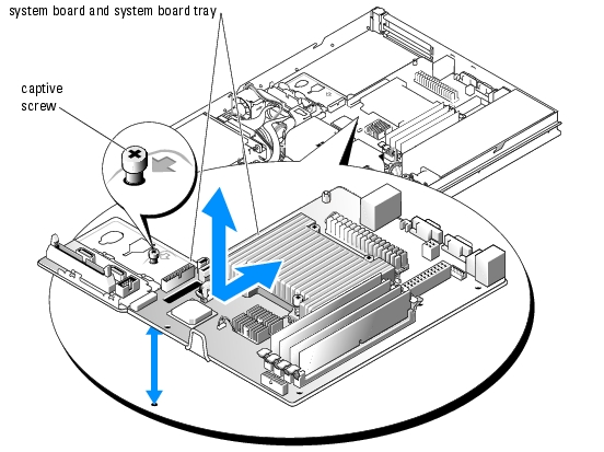
- Loosen the captive screw that secures the system board tray to the chassis floor. See
Figure 7-3.
- Using the tab on the system board tray, slide the system board forward (toward the front of
the system) and lift the assembly up and out of the chassis. See Figure 7-3.
- Lay the system board tray down on a smooth, nonconductive work surface.
Figure 7-3. Removing the System Board Assembly
Installing the System Board Assembly
|
|
CAUTION: Only trained service technicians are authorized to remove the system cover and access any of the components inside the system. Before performing any procedure, see your Product Information Guide for complete information about safety precautions, working inside the computer and protecting against electrostatic discharge. |
- Unpack the new system board assembly.
- Align the system board tray so that the tabs on the chassis floor slide into the notches in the
system board tray.
- Slide the system board tray backward until it stops.
- Using a #2 Phillips screwdriver, tighten the screw that secures the system board tray to the
chassis. See Figure 7-3.
- Install the fan module. See "Installing the Fan Assembly" in "Installing System Components."
- Connect the two power cables to the 12V and PWR_CONN connectors on the system board.
See Figure A-3.
- Connect the chassis intrusion cable to the INTRUSION_SWITCH connector on the system
board.
- Install the riser card. See "Installing the Riser Card" in "Installing System Components."
- Using a #2 Phillips screwdriver, tighten the two screws that secure the riser card to the system
board.
- Install any PCI expansion cards that you removed. See "Installing an Expansion Card" in
"Installing System Components."
- Connect the hard-drive interface cables:
- If SCSI hard drives are installed, connect the interface cable to the PCI controller card.
- If SATA hard drives are installed, connect the interface cable to the SATA_0 and SATA_1
connectors on the daughter card. See Figure A-3.
- Install the processor and heat sink. See "Replacing the Processor" in "Installing System
Components."
- Install the memory modules. See "Installing Memory Modules" in "Installing System
Components."
|
|
NOTE: Install the memory modules as noted in step 4 of the procedure in "Removing the System Board Assembly." |
- Connect the two control-panel interface cables to the FRONT_PANEL connector on the
system board and the USB_CONN connector on the daughter card. See Figure A-3.
- If applicable, connect the optical drive interface cable to the PRI_IDE1 connector on the
daughter card. See Figure A-3.
- Install the cooling shroud. See "Replacing the Processor" in "Installing System Components."
- Close the system. See "Closing the System" in "Troubleshooting Your System."
Back to Contents Page