Back to Contents Page
Troubleshooting Your System
Dell™ PowerEdge™ 2800 Systems Installation and Troubleshooting Guide
Safety First—For You and Your System
To perform certain procedures in this document, you must remove the system cover and work inside the system. While working inside the system, do not attempt to service the system except as explained in this guide and elsewhere in your system documentation.

|
CAUTION: Only trained service technicians are authorized to remove the system cover and access any of the components inside the system. See your Product Information Guide for complete information about safety precautions, working inside the computer, and protecting against electrostatic discharge. |
Start-Up Routine
Look and listen during the system's start-up routine for the indications described in Table 5-1.
Table 5-1. Start-Up Routine Indications
Checking Basic Power Problems
- If the power indicator on the system front panel or power supply does not indicate that power
is available to the system, ensure that the power cable is securely connected to the power
supply.
- If the system is connected to a PDU or UPS, turn the PDU or UPS off and then on.
- If the PDU or UPS is not receiving power, plug it into another electrical outlet. If it still is not
receiving power, try another PDU or UPS.
- Reconnect the system to the electrical outlet and turn on the system.
If the system still is not working properly, see "Troubleshooting Redundant Power Supplies."
Checking the Equipment
This section provides troubleshooting procedures for external devices attached to the system, such as the monitor, keyboard, or mouse. Before you perform any of the procedures, see "Troubleshooting External Connections."
Troubleshooting External Connections
Loose or improperly connected cables are the most likely source of problems for the system, monitor, and other peripherals (such as a printer, keyboard, mouse, or other external device). Ensure that all external cables are securely attached to the external connectors on your system. See Figure 2-1 and Figure 2-2 for the front-panel and back-panel connectors on your system.
Troubleshooting the Video Subsystem
Problem
- Monitor is not working properly.
- Video memory is faulty.
Action
- Check the system and power connections to the monitor.
- Run the appropriate online diagnostic test. See "Using Server Administrator Diagnostics" in
"Running System Diagnostics."
If the tests run successfully, the problem is not related to video hardware. See "Finding Software Solutions."
If the tests fail, see "Getting Help."
Troubleshooting the Keyboard
Problem
- System message indicates a problem with the keyboard.
- Keyboard is not functioning properly.
Action
- Run the appropriate online diagnostic test. See "Using Server Administrator Diagnostics" in
"Running System Diagnostics."
- Examine the keyboard and its cable for signs of damage.
- Swap the faulty keyboard with a working keyboard.
If the problem is resolved, replace the faulty keyboard.
- If the keyboard is a USB keyboard, enter the System Setup program and ensure that the USB
ports are enabled. See "Using the System Setup Program" in your User's Guide.
If the problem is not resolved, see "Getting Help."
Troubleshooting the Mouse
Problem
- System message indicates a problem with the mouse.
- Mouse is not functioning properly.
Action
- Run the appropriate online diagnostic test. See "Using Server Administrator Diagnostics" in
"Running System Diagnostics."
If the test fails, continue to the next step.
- Examine the mouse and its cable for signs of damage.
If the mouse is not damaged, go to step 5.
If the mouse is damaged, continue to the next step.
- Swap the faulty mouse with a working mouse.
If the problem is resolved, replace the faulty mouse.
- If the mouse is a USB mouse, enter the System Setup program and ensure that the USB ports
are enabled. See "Using the System Setup Program" in your User's Guide.
- If the problem is not resolved, see "Getting Help."
Troubleshooting Basic I/O Functions
Problem
- Error message indicates a problem with the serial port.
- Device connected to the serial port is not operating properly.
Action
- Enter the System Setup program and ensure that the serial port is enabled. See "Using the
System Setup Program" in the User's Guide.
- If the problem is confined to a particular application, see the application documentation for
specific port configuration requirements that the program may require.
- Run the appropriate online diagnostic test. See "Using Server Administrator Diagnostics" in
"Running System Diagnostics."
If the tests run successfully but the problem persists, see the appropriate procedure—"Troubleshooting a Serial I/O Device" or "Troubleshooting a Non-USB Parallel Printer."
Troubleshooting a Serial I/O Device
Problem
- Device connected to the serial port is not operating properly.
Action
- Turn off the system and any peripheral devices connected to the serial port.
- Swap the serial interface cable with a working cable, and turn on the system and the serial
device.
If the problem is resolved, replace the interface cable.
- Turn off the system and the serial device, and swap the device with a comparable device.
- Turn on the system and the serial device.
If the problem is resolved, replace the serial device.
If the problem persists, see "Getting Help."
Troubleshooting a USB Device
Problem
- System message indicates a problem with a USB device.
- Device connected to a USB port is not operating properly.
Action
- Enter the System Setup program, and ensure that the USB ports are enabled. See "Using the
System Setup Program" in your User's Guide.
- Turn off the system and any USB devices.
- Disconnect the USB devices, and connect the malfunctioning device to another USB
connector.
- Turn on the system and the reconnected device.
If the problem is resolved, the USB connector might be defective. See "Getting Help."
- If possible, swap the interface cable with a working cable.
If the problem is resolved, replace the interface cable.
- Turn off the system and the USB device, and swap the device with a comparable device.
- Turn on the system and the USB device.
If the problem is resolved, replace the USB device.
If the problem persists, see "Getting Help."
Troubleshooting a Non-USB Parallel Printer
Problem
- Parallel printer is not operating properly.
- Parallel printer interface cable.
Action
- Turn off the system and the parallel printer.
- Swap the parallel printer interface cable with a known working cable, and turn on the system
and the printer.
- Attempt a print operation.
- If the print operation is successful, replace the interface cable (see "Getting Help").
- Run the printer's self-test.
- If the self-test fails, the printer is malfunctioning (see "Getting Help").
|
|
CAUTION: Only trained service technicians are authorized to remove the system cover and access any of the components inside the system. See your Product Information Guide for complete information about safety precautions, working inside the computer, and protecting against electrostatic discharge. |
- Open the system. See "Opening the System."
Ensure that the cable leading to the parallel port on the system back panel is properly connected to the parallel port connector on the system board. See Figure A-3.
- Close the system. See "Closing the System."
- Reconnect the system to the electrical outlet, and turn on the system and attached
peripherals.
- If the problem is not resolved, see "Getting Help."
Troubleshooting a NIC
Problem
- NIC cannot communicate with network.
Action
- Run the appropriate online diagnostic test. See "Using Server Administrator Diagnostics" in
"Running System Diagnostics."
- Enter the System Setup program and confirm that the NICs are enabled. See "Using the
System Setup Program" in your User's Guide.
- Check the appropriate indicator on the NIC connector. See "NIC Indicator Codes" in
"Indicators, Messages, and Codes."
- If the link indicator does not light, check all cable connections.
- If the activity indicator does not light, the network driver files might be damaged or missing.
Remove and reinstall the drivers if applicable. See the NIC's documentation.
- Use another connector on the switch or hub.
If you are using a NIC card instead of an integrated NIC, see the documentation for the NIC card.
- Ensure that the appropriate drivers are installed and the protocols are bound. See the NIC's
documentation.
- Ensure that the NICs, hubs, and switches on the network are all set to the same data
transmission speed. See the network equipment documentation.
- Ensure that all network cables are of the proper type and do not exceed the maximum length.
See "Network Cable Requirements" in your User's Guide.
Responding to a Systems Management Software
Alert Message
Systems management software monitors critical system voltages and temperatures, fans, and hard drives in the system. Alert messages appear in the Alert Log window. For information about the Alert Log window, see the systems management software documentation.
Inside the System
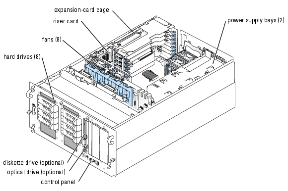
In Figure 5-1, the bezel and system cover are removed to provide an interior view of the system.
Figure 5-1. Inside the System
The system board holds the system's control circuitry and other electronic components. The processor and memory are installed directly on the system board. Using a riser card, the system can accommodate up to seven expansion cards.
The SCSI backplane supports up to eight SCSI hard drives. A removable drive carrier supports an optional diskette drive and optional optical drive. The peripheral bays provide space for two half-height or one full-height 5 1/4-inch form factor devices, or two additional SCSI hard drives and a half-height 5 1/4-inch form factor device. Power is supplied to the system board and drives through one or two (optional) power supplies.
Opening the System
The system is enclosed by an optional bezel and cover. To upgrade or troubleshoot the system, remove the bezel and cover to access the drives and internal system components.

|
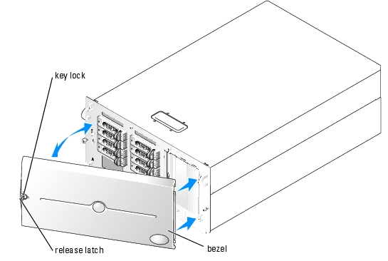
NOTE: The following procedure applies to rack systems. The procedure for a tower system is similar, except the keylock and release latch are at the upper edge of the bezel when the system is upright. |
- If applicable, remove the bezel. See Figure 5-2.
- Unlock the keylock at the left end of the bezel.
- While grasping the bezel, depress the release latch on the left edge of the bezel, adjacent
to the keylock.
- Rotate the left end of the bezel away from the front panel.
- Unhook the right end of the bezel and pull the bezel away from the system.
Figure 5-2. Installing and Removing the Optional Bezel
|
|
CAUTION: Only trained service technicians are authorized to remove the system cover and access any of the components inside the system. See your Product Information Guide for complete information about safety precautions, working inside the computer, and protecting against electrostatic discharge. |
- Unless you are installing a hot-plug component such as a cooling fan or hot-plug expansion
card, turn off the system and attached peripherals, and disconnect the system from the
electrical outlet and peripherals.
- If you are working with a tower system, place the system on its side as shown in Figure 5-2.
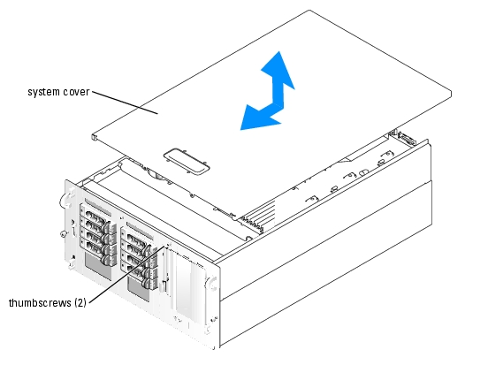
- To remove the system cover, loosen the two thumbscrews at the front of the system. See
Figure 5-3.
- Slide the cover backward about 1.3 cm (0.5 inch), and grasp the cover on both sides.
- Carefully lift the cover away from the system.
Figure 5-3. Installing and Removing the System Cover
Closing the System
- Ensure that you did not leave tools or parts inside the system.
- Place the cover over the sides of the chassis, and slide the cover forward.
- Tighten the two thumbscrews at the front of the system to secure the cover. See Figure 5-3.
- Reconnect the peripheral cables.
- Reconnect the system to the electrical outlet, and turn on the system.
- To replace the optional bezel, hook the right end of the bezel onto the chassis, then fit the
free end of the bezel onto the system. Secure the bezel with the keylock. See Figure 5-2.
Troubleshooting a Wet System
Problem
- Liquid spilled on the system.
- Excessive humidity.
Action
|
|
CAUTION: Only trained service technicians are authorized to remove the system cover and access any of the components inside the system. See your Product Information Guide for complete information about safety precautions, working inside the computer, and protecting against electrostatic discharge. |
- Turn off the system and attached peripherals, and disconnect the system from the electrical
outlet.
- Open the system. See "Opening the System."
- Remove the expansion card cage from the system. See "Removing the Expansion-Card Cage"
in "Installing System Components."
- Remove all expansion cards installed in the system. See "Removing an Expansion Card" in
"Installing System Components."
- Remove all memory modules installed in the system. See "Removing Memory Modules" in
"Installing System Components."
- Remove the processor(s) from the system. See "Replacing a Processor" in "Installing System
Components."
- Let the system dry thoroughly for at least 24 hours.
- Replace the processor(s), memory modules, and expansion cards. See "Replacing a Processor,"
"Installing Memory Modules," and "Installing an Expansion Card" in "Installing System
Components."
- Replace the expansion card cage. See "Installing the Expansion-Card Cage" in "Installing
System Components."
- Close the system. See "Closing the System."
- Reconnect the system to the electrical outlet, and turn on the system and peripherals.
If the system does not start properly, see "Getting Help."
- Run the appropriate online diagnostic test. See "Using Server Administrator Diagnostics" in
"Running the System Diagnostics."
If the tests fail, see "Getting Help."
Troubleshooting a Damaged System
Problem
- System was dropped or damaged.
Action
|
|
CAUTION: Only trained service technicians are authorized to remove the system cover and access any of the components inside the system. See your Product Information Guide for complete information about safety precautions, working inside the computer, and protecting against electrostatic discharge. |
- Open the system. See "Opening the System."
- Ensure that the following components are properly installed:
- Expansion-card cage
- Expansion cards
- Memory modules
- Processor(s)
- Power supplies
- Fans
- Hard drives
- Ensure that all cables are properly connected.
- Close the system. See "Closing the System."
- Run the system board tests in the system diagnostics. See "Running the System Diagnostics."
If the tests fail, see "Getting Help."
Troubleshooting the System Battery
Problem
- System message indicates a problem with the battery.
- System Setup program loses system configuration information.
- System date and time do not remain current.
|
|
NOTE: If the system is turned off for long periods of time (for weeks or months), the NVRAM may lose its system configuration information. This situation is caused by a defective battery. |
Action
- Re-enter the time and date through the System Setup program. See "Using the System Setup
Program" in your User's Guide.
- Turn off the system and disconnect it from the electrical outlet for at least one hour.
- Reconnect the system to the electrical outlet and turn on the system.
- Enter the System Setup program.
If the date and time are not correct in the System Setup program, replace the battery. See "System Battery" in "Installing System Components."
If the problem is not resolved by replacing the battery, see "Getting Help."
|
|
NOTE: Some software may cause the system time to speed up or slow down. If the system seems to operate normally except for the time kept in the System Setup program, the problem may be caused by software rather than by a defective battery. |
Troubleshooting Redundant Power Supplies
Problem
- System status indicator is amber.
- Power supply fault indicator is amber.
Action
- Run the appropriate online diagnostics test. See "Using Server Administrator Diagnostics" in
"Running the System Diagnostics."
- Identify the faulty power supply.
The power supply's fault indicator is lit. See "Power Indicator Codes" in "Indicators, Messages, and Codes."

|
NOTICE: The power supplies are hot-pluggable. Remove and install only one power supply at a time in a system that is powered on. The system is in the redundant mode when two power supplies are installed and both power supplies are connected to an AC power source. Operating the system with only one power supply installed and without a power supply blank installed for extended periods of time can cause the system to overheat. |
- Ensure that the power supply is properly installed by removing and reinstalling it. See "Power
Supplies" in "Installing System Components."
|
|
NOTE: After installing a power supply, allow several seconds for the system to recognize the power supply and to determine if it is working properly. The power indicator turns green to signify that the power supply is functioning properly. See "Power Indicator Codes" in "Indicators, Messages, and Codes." |
If the problem persists, remove the faulty power supply. See "Removing a Power Supply" in "Installing System Components."
- Install a new power supply. See "Installing a Power Supply" in "Installing System
Components."
If the problem persists, see "Getting Help."
Troubleshooting System Cooling Problems
Problem
- System status indicator is amber.
- Systems management software issues a fan-related error message.
Action
|
|
CAUTION: Only trained service technicians are authorized to remove the system cover and access any of the components inside the system. See your Product Information Guide for complete information about safety precautions, working inside the computer, and protecting against electrostatic discharge. |
- Run the appropriate diagnostic test. See "Using Server Administrator Diagnostics" in Running
System Diagnostics."
- Open the system. See "Opening the System."
- Locate the fan referenced by the systems management software or diagnostics.
See Figure A-3 for the relative location of each fan.
- Ensure that the faulty fan is firmly seated in the fan bracket, to ensure contact with the fan
power connector on the system board.
- Check that cables are not blocking the airflow within the system.
- Close the system. See "Closing the System."
- Reconnect the system to the electrical outlet, and turn on the system and attached
peripherals.
- If the problem is not resolved, install a new fan. See "Fans" in "Installing System
Components."
- If the replacement fan does not operate, see "Getting Help."
Troubleshooting System Memory
Problem
- Faulty memory module.
- Faulty system board.
- System status indicator is amber.
- LCD error code or system beep code indicates a memory problem.
- Systems management software issues a memory-related message through the LCD display or systems management software.
Action
Memory-related beep code during system startup.
|
|
CAUTION: Only trained service technicians are authorized to remove the system cover and access any of the components inside the system. See your Product Information Guide for complete information about safety precautions, working inside the computer, and protecting against electrostatic discharge. |
- Turn off the system and attached peripherals, and disconnect the system from the electrical
outlet.
- Open the system. See "Opening the System."
- Reseat the memory modules in their sockets. See "Installing Memory Modules" in "Installing
System Components."
- Close the system. See "Closing the System."
- Reconnect the system to the electrical outlet, and turn on the system and attached
peripherals.
If there is no memory-related beep code, the problem is resolved.
- Turn off the system and attached peripherals, and disconnect the system from the electrical
outlet.
- Open the system. See "Opening the System."
- Remove all memory modules from the system. See "Removing Memory Modules" in
"Installing System Components."
- Replace one of the memory modules in socket DIMM1_B.
- Close the system. See "Closing the System."
- Reconnect the system to the electrical outlet, and turn on the system and attached
peripherals.
- If there is no memory-related beep code, the memory module is not faulty.
If the beep code reoccurs, the memory module is faulty and should be replaced.
- Perform the following steps:
- Turn off the system and attached peripherals, and disconnect the system from its
electrical outlet.
- Open the system. See "Opening the System."
- Repeat step c through step f in step 6 for each memory module installed.
- If you have tested all the memory modules and the problem persists, or none of the memory
modules passes, the system board is faulty. See "Getting Help."
The system starts up successfully but there are memory-related error messages.
|
|
CAUTION: Only trained service technicians are authorized to remove the system cover and access any of the components inside the system. See your Product Information Guide for complete information about safety precautions, working inside the computer, and protecting against electrostatic discharge. |
- Turn off the system and attached peripherals, and disconnect the system from the electrical
outlet.
- Open the system. See "Opening the System."
- Ensure that the memory modules are populated correctly. See "General Memory Module
Installation Guidelines" in "Installing System Components."
If the memory modules are populated correctly, continue to the next step.
- Reseat the memory modules in their sockets. See "Installing Memory Modules" in "Installing
System Components."
- Close the system. See "Closing the System."
- Reconnect the system to the electrical outlet, and turn on the system and attached
peripherals.
If there is no memory-related error message, the problem is resolved.
If the problem persists, see "Getting Help."
There are memory-related error messages on the system LCD, or in the SEL.
- Enter the System Setup program and disable the Redundant Memory option, if applicable.
See "Using the System Setup Program" in your User's Guide.
- Run the appropriate online diagnostic test. See "Using Server Administrator Diagnostics" in
"Running System Diagnostics."
- Replace the memory module(s) identified by the diagnostics. See "Installing Memory
Modules" in "Installing System Components."
- Enter the System Setup program and enable the Redundant Memory option, if disabled in
step 1.
- Restart the system. If there are still memory-related errors on the system LCD, or in the SEL,
see "Getting Help."
Troubleshooting a Diskette Drive
Problem
- Error message indicates a problem with the optional diskette drive.
Action
|
|
CAUTION: Only trained service technicians are authorized to remove the system cover and access any of the components inside the system. See your Product Information Guide for complete information about safety precautions, working inside the computer, and protecting against electrostatic discharge. |
- Enter the System Setup program and verify that the diskette controller is enabled and the
diskette drive is configured correctly. See "Using the System Setup Program" in the User's
Guide.
- Run the appropriate online diagnostic test. See "Using Server Administrator Diagnostics" in
"Running System Diagnostics."
- Turn off the system and attached peripherals, and disconnect the system from the electrical
outlet.
- Ensure that the diskette/optical drive carrier is fully inserted in the system chassis. See
Figure 7-3.
- Reconnect the system to the electrical outlet, and turn on the system and attached
peripherals.
- Run the appropriate online diagnostic test to see whether the diskette drive works correctly.
- Turn off the system and attached peripherals, and disconnect the system from its electrical
outlet.
- Open the system. See "Opening the System."
- Remove all expansion cards installed in the system. See "Removing an Expansion Card" in
"Installing System Components."
- Close the system. See "Closing the System."
- Reconnect the system to the electrical outlet, and turn on the system and attached
peripherals.
- Run the appropriate online diagnostic test to see whether the diskette drive works correctly.
If the tests run successfully, an expansion card may be conflicting with the diskette drive logic, or an expansion card may be faulty. Continue to the next step.
If the tests fail, see "Getting Help."
- Turn off the system and attached peripherals, and disconnect the system from the electrical
outlet.
- Open the system. See "Opening the System."
- Reinstall one of the expansion cards you removed in step 9. See "Installing an Expansion
Card" in "Installing System Components."
- Close the system. See "Closing the System."
- Reconnect the system to the electrical outlet, and turn on the system and attached
peripherals.
- Run the appropriate online diagnostic test to see whether the diskette drive works correctly.
- Repeat step 13 through step 18 until all expansion cards are reinstalled or one of the
expansion cards causes the tests to fail.
If the problem is not resolved, see "Getting Help."
Troubleshooting an Optical Drive
Problem
- System cannot read data from a CD.
- Optical drive indicator does not blink during boot.
Action
|
|
CAUTION: Only trained service technicians are authorized to remove the system cover and access any of the components inside the system. See your Product Information Guide for complete information about safety precautions, working inside the computer, and protecting against electrostatic discharge. |
- Try using a different CD that you know works properly.
- Enter the System Setup program and ensure that the drive's IDE controller is enabled. See
"Using the System Setup Program" in the User's Guide.
- Run the appropriate online diagnostic test. See "Using Server Administrator Diagnostics" in
"Running System Diagnostics."
- Turn off the system and attached peripherals, and disconnect the system from the electrical
outlet.
- Remove and reinstall the diskette/optical drive carrier, making sure it is fully inserted in the
system chassis. See Figure 7-3.
- Reconnect the system to the electrical outlet, and turn on the system and attached
peripherals.
If the problem is not resolved, see "Getting Help."
Troubleshooting a SCSI Tape Drive
Problem
- Defective tape drive.
- Defective tape cartridge.
- Missing or corrupted tape-backup software or tape drive device driver.
- Defective optional SCSI controller card.
Action
|
|
CAUTION: Only trained service technicians are authorized to remove the system cover and access any of the components inside the system. See your Product Information Guide for complete information about safety precautions, working inside the computer, and protecting against electrostatic discharge. |
- Run the System Setup program and ensure that the secondary SCSI channel is enabled and
set to SCSI.
See "Using the System Setup Program" in the User's Guide.
- Remove the tape cartridge you were using when the problem occurred, and replace it with a
tape cartridge that you know works.
- Ensure that the SCSI device drivers for the tape drive are installed and are configured
correctly.
- Reinstall the tape-backup software as instructed in the tape-backup software documentation.
- Ensure that the tape drive's interface cable is connected to the tape drive and SCSI controller
card, or the external SCSI connector on the system back panel. SeeFigure 2-2.
- Verify that the tape drive is configured for a unique SCSI ID number and that the tape drive
is terminated or not terminated, based on the interface cable used to connect the drive.
See the documentation for the tape drive for instructions on selecting the SCSI ID number and enabling or disabling termination.
- Run the appropriate online diagnostics tests. See "Using Server Administrator Diagnostics" in
"Running System Diagnostics."
- Turn off the system and attached peripherals, and disconnect the system from the electrical
outlet.
- Open the system. See "Opening the System."
- If the drive is connected to an optional SCSI controller card, check that the card is firmly
seated in its connector. See "Installing an Expansion Card" in "Installing System
Components."
- If the drive is connected to the integrated SCSI controller on the riser card using the optional
external SCSI connector on the system back panel, check the cable connection to the riser
card.
- Close the system. See "Closing the System."
- Reconnect the system to the electrical outlet, and turn on the system, including attached
peripherals.
- If the problem is not resolved, see the documentation for the tape drive for additional
troubleshooting instructions.
- If you cannot resolve the problem, see "Getting Help" for information on obtaining technical
assistance.
Troubleshooting SCSI Hard Drives
Problem
- Device driver error.
- Hard drive not recognized by the system.
Action
|
|
CAUTION: Only trained service technicians are authorized to remove the system cover and access any of the components inside the system. See your Product Information Guide for complete information about safety precautions, working inside the computer, and protecting against electrostatic discharge. |
|
|
NOTICE: This procedure can destroy data stored on the hard drive. Before you continue, back up all files on the hard drive. |
- Run the appropriate online diagnostic test. See "Using Server Administrator Diagnostics" in
"Running System Diagnostics."
For information about testing the controller, see the SCSI or RAID controller's documentation.
If the tests fail, continue to the next step.
- Run the System Setup program and ensure that the SCSI controller is enabled.
See "Using the System Setup Program" in the User's Guide.
- If the integrated SCSI host adapter controls the SCSI hard drives, restart the system and press
<Ctrl><a> to enter the SCSI configuration utility program.
|
|
NOTE: If your system has an optional RAID controller card or RAID on motherboard (ROMB) is enabled, restart the system and press <Ctrl><a> or <Ctrl><m>, depending on the utility. See the documentation supplied with the controller for information about the configuration utility. |
- Ensure that the primary SCSI channel is enabled, and restart the system.
See the documentation supplied with the controller for information about the configuration utility.
- Verify that the device drivers are installed and configured correctly. See the operating system
documentation.
- Remove the hard drive and install it in another drive bay.
- If the problem is resolved, reinstall the hard drive in the original bay. See "Installing a SCSI
Hard Drive" in "Installing Drives."
If the hard drive functions properly in the original bay, the drive carrier could have intermittent problems. Replace the drive carrier. See "Getting Help."
If the problem persists, the SCSI backplane board has a defective connector. See "Getting Help."
- Check the SCSI cable connections inside the system:
- Turn off the system, including any attached peripherals, and disconnect the system from
the electrical outlet.
- Open the system. See "Opening the System."
- Verify that the SCSI cable is securely connected to the SCSI backplane, and to the SCSI
host adapter on the riser card, or a SCSI host adapter card installed in an expansion slot.
- Close the system. See "Closing the System."
- Format and partition the hard drive. See the operating system documentation.
- If possible, restore the files to the drive.
If the problem persists, see "Getting Help."
Troubleshooting the Integrated RAID Controller
Problem
- Error message indicates a problem with the optional integrated RAID controller.
Action
|
|
CAUTION: Only trained service technicians are authorized to remove the system cover and access any of the components inside the system. See your Product Information Guide for complete information about safety precautions, working inside the computer, and protecting against electrostatic discharge. |
- Run the appropriate online diagnostic test. See "Using Server Administrator Diagnostics" in
"Running System Diagnostics."
- Enter the System Setup program and ensure that the Embedded RAID Controller option is
set to RAID Enabled. See "Using the System Setup Program" in your User's Guide.
- Ensure that the integrated RAID controller is configured properly. See the RAID controller's
documentation for information about configuration settings.
If the problem is not resolved, continue to the next step.
- Turn off the system and attached peripherals, and disconnect the system from its electrical
outlet.
- Open the system. See "Opening the System."
- Ensure that the following RAID components are properly installed:
- Memory module
- RAID key
- Battery
See "Activating the Optional Integrated RAID Controller" in "Installing Drives."
- Close the system. See "Closing the System."
- Reconnect the system to its electrical outlet, and turn on the system and attached
peripherals.
If the problem is not resolved, continue to the next step.
- Turn off the system and attached peripherals, and disconnect the system from its electrical
outlet.
- Open the system. See "Opening the System."
|
|
CAUTION: Replace the battery only with the same or equivalent type recommended by the manufacturer. Discard used batteries according to the manufacturer's instructions. See the Product Information Guide for more information. |
- Replace the RAID battery. See "Activating the Optional Integrated RAID Controller" in
"Installing Drives."
- Close the system. See "Closing the System."
- Reconnect the system to its electrical outlet, and turn on the system and attached
peripherals.
If the problem persists, see "Getting Help."
Troubleshooting a RAID Controller Card
|
|
NOTE: When troubleshooting a RAID controller card, also see the documentation for your operating system and the RAID controller. |
Problem
- Error message indicates a RAID controller problem.
- RAID controller performs incorrectly or not at all.
Action
|
|
CAUTION: Only trained service technicians are authorized to remove the system cover and access any of the components inside the system. See your Product Information Guide for complete information about safety precautions, working inside the computer, and protecting against electrostatic discharge. |
- Run the appropriate online diagnostic test. See "Using Server Administrator Diagnostics" in
"Running the System Diagnostics."
- Turn off the system and attached peripherals, and disconnect the system from the electrical
outlet.
- Open the system. See "Opening the System."
- Ensure that the controller card is firmly seated in its connector. See "Installing an Expansion
Card" in "Installing System Components."
- Ensure that the appropriate cables are firmly connected to their corresponding connectors on
the controller card and SCSI backplane.
- Close the system. See "Closing the System."
- Reconnect the system to the electrical outlet, and turn on the system and attached
peripherals.
If the problem persists, see the RAID controller's documentation for more information on troubleshooting.
Troubleshooting Expansion Cards
|
|
NOTE: When troubleshooting an expansion card, see the documentation for your operating system and the expansion card. |
Problem
- Error message indicates a problem with an expansion card.
- Expansion card performs incorrectly or not at all.
Action
|
|
CAUTION: Only trained service technicians are authorized to remove the system cover and access any of the components inside the system. See your Product Information Guide for complete information about safety precautions, working inside the computer, and protecting against electrostatic discharge. |
- Run the appropriate online diagnostic test. See "Using Server Administrator Diagnostics" in
"Running System Diagnostics."
- Turn off the system and attached peripherals, and disconnect the system from the electrical
outlet.
- Open the system. See "Opening the System."
- Ensure that the expansion-card cage is securely installed. See "Removing the Expansion-Card
Cage" in "Installing System Components."
- Ensure that each expansion card is firmly seated in its connector. See "Installing an Expansion
Card" in "Installing System Components."
- Close the system. See "Closing the System."
- Reconnect the system to the electrical outlet, and turn on the system and attached
peripherals.
If the problem persists, go to the next step.
- Turn off the system and attached peripherals, and disconnect the system from the electrical
outlet.
- Open the system. See "Opening the System."
- Remove all expansion cards installed in the system. See "Removing an Expansion Card" in
"Installing System Components."
- Close the system. See "Closing the System."
- Reconnect the system to the electrical outlet, and turn on the system and attached
peripherals.
- Run the appropriate online diagnostic test.
If the tests fail, see "Getting Help."
- For each expansion card you removed in step 10, perform the following steps:
- Turn off the system and attached peripherals, and disconnect the system from the
electrical outlet.
- Open the system. See "Opening the System."
- Reinstall one of the expansion cards. See "Installing an Expansion Card."
- Close the system. See "Closing the System."
- Run the appropriate diagnostic test.
If the tests fail, see "Getting Help."
Troubleshooting the Microprocessors
Problem
- Error message indicates a processor problem.
- A heat sink is not installed for each processor.
Action
|
|
CAUTION: Only trained service technicians are authorized to remove the system cover and access any of the components inside the system. See your Product Information Guide for complete information about safety precautions, working inside the computer, and protecting against electrostatic discharge. |
- Run the appropriate online diagnostics test. See "Using Server Administrator Diagnostics" in
"Running the System Diagnostics."
- Turn off the system and attached peripherals, and disconnect the system from the electrical
outlet.
- Open the system. See "Opening the System."
- Remove the processor fan bracket from the system. See "Removing the Center Fan Bracket"
in "Installing System Components."
- Ensure that each processor and heat sink are properly installed. See "Replacing a Processor" in
"Installing System Components."
- Replace the processor fan bracket in the system. See "Removing the Center Fan Bracket" in
"Installing System Components."
- Close the system. See "Closing the System."
- Reconnect the system to the electrical outlet, and turn on the system and attached
peripherals.
- Run the appropriate online diagnostic test.
If the tests fail or the problem persists, continue to the next step.
- Turn off the system and attached peripherals, and disconnect the system from the electrical
outlet.
- Open the system. See "Opening the System."
- Remove the second processor, leaving only processor 1 installed. See "Replacing a Processor"
in "Installing System Components."
To locate the processors, see Figure A-3.
If only one processor is installed, see "Getting Help."
- Close the system. See "Closing the System."
- Reconnect the system to the electrical outlet, and turn on the system and attached
peripherals.
- Run the appropriate online diagnostic test.
If the tests complete successfully, go to step 21.
- Turn off the system and attached peripherals, and disconnect the system from the electrical
outlet.
- Open the system. See "Opening the System."
- Replace processor 1 with another processor of the same capacity. See "Replacing a Processor"
in "Installing System Components."
- Close the system. See "Closing the System."
- Run the appropriate online diagnostic test.
If the tests complete successfully, replace processor 1. See "Getting Help."
- Turn off the system and attached peripherals, and disconnect the system from the electrical
outlet.
- Open the system. See "Opening the System."
- Reinstall the second processor that you removed in step 12. See "Replacing a Processor" in
"Installing System Components."
- Close the system. See "Closing the System."
- Reconnect the system to the electrical outlet, and turn on the system and attached
peripherals.
If the problem persists, see "Getting Help."
Back to Contents Page
 Safety First—For You and Your System