Back to Contents Page
Installing Drives
Dell™ PowerEdge™ 2800 Systems Installation and Troubleshooting Guide
 Installing SCSI Hard Drives
Installing a Diskette Drive
Removing the Peripheral Bay Filler Panel
(Tower Systems Only)
Installing an Optical Drive
Installing an Internal SCSI Tape Drive
Connecting an External SCSI Tape Drive
Configuring the Boot Drive
Activating the Optional Integrated RAID Controller
Installing a RAID Controller Card
SCSI Hard-Drive Cabling Guidelines
Your system features eight standard internal hard-drive bays that accommodate up to eight SCSI hard drives. Systems with an optional RAID controller card or optional ROMB support hot-plug SCSI drive operation.
The system's two peripheral bays can accommodate up to two 5-1/4-inch form-factor devices (such as tape drives) or an optional 1x2 SCSI backplane to enable installation of two additional SCSI hard drives.
Installing SCSI Hard Drives
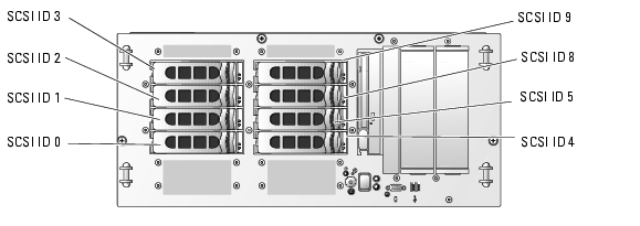
Figure 7-1 shows the SCSI ID numbers of the eight standard drive bays. (SCSI ID 6 and SCSI ID 7 are reserved for use by the system's integrated SCSI host adapter and SCSI enclosure management controller.)
Figure 7-1. Hard-Drive SCSI ID Numbers
Before You Begin
SCSI hard drives are supplied in special drive carriers that fit in the hard-drive bays.

|
NOTICE: Before attempting to remove or install a drive while the system is running, see the documentation for the optional RAID controller card or optional ROMB to ensure that the host adapter is configured correctly to support hot-plug drive removal and insertion. |

|
NOTE: It is recommended that you use only drives that have been tested and approved for use with the SCSI backplane board. |
You may need to use different programs than those provided with the operating system to partition and format SCSI hard drives.
|
|
NOTICE: Do not turn off or reboot your system while the drive is being formatted. Doing so can cause a drive failure. |
When you format a high-capacity SCSI hard drive, allow enough time for the formatting to be completed. Long format times for these drives are normal. A 9-GB hard drive, for example, can take up to 2.5 hours to format.
Installing a SCSI Hard Drive
|
|
NOTICE: Hot-plug drive installation is not supported for systems without an optional RAID controller card or optional ROMB. |
- If the system does not have an optional RAID controller card or optional riser card with
ROMB, shut down the system.
- Remove the front bezel, if attached. See "Opening the System" in "Troubleshooting Your
System."
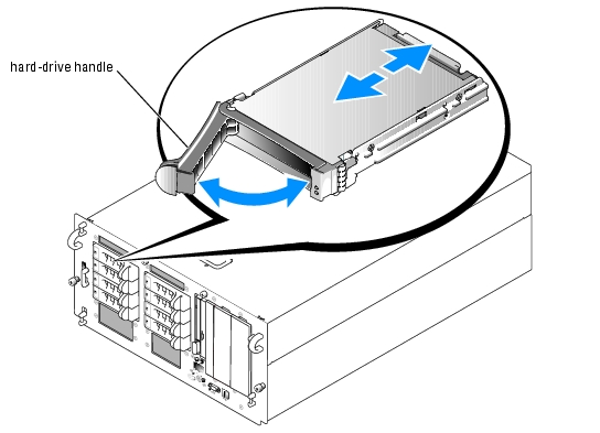
- Open the hard-drive handle. See Figure 7-2.
Figure 7-2. Installing a SCSI Hard Drive
- Insert the hard drive into the drive bay. See Figure 7-2.
- Close the hard-drive handle to lock the drive in place.
- Replace the front bezel, if it was removed in step 2.
- If the hard drive is a new drive, run the SCSI Controllers test in the system diagnostics.
Removing a SCSI Hard Drive
|
|
NOTICE: Hot-plug drive removal is not supported for systems without an optional RAID controller card or optional ROMB. |
- If the system does not have an optional RAID controller card or optional ROMB, shut down
the system.
- Remove the front bezel, if attached. See "Opening the System" in "Troubleshooting Your
System."
- For systems with a RAID controller card or ROMB, power down the hard-drive bay and wait
until the SCSI hard-drive indicators on the drive carrier signal that the drive can be removed
safely.
If the drive has been online, the green power on/fault indicator will flash as the drive is powered down. When both drive indicators are off, the drive is ready for removal.
- Open the hard-drive handle to release the drive.
- Slide the hard drive out until it is free of the drive bay.
- Replace the front bezel, if it was removed in step 2.
Installing a Diskette Drive

|
CAUTION: Only trained service technicians are authorized to remove the system cover and access any of the components inside the system. See your Product Information Guide for complete information about safety precautions, working inside the computer, and protecting against electrostatic discharge. |
- Turn off the system, including any attached peripherals, and disconnect the system from the
electrical outlet.
- Remove the front bezel, if attached. See "Opening the System" in "Troubleshooting Your
System."
- Open the system. See "Opening the System" in "Troubleshooting Your System."
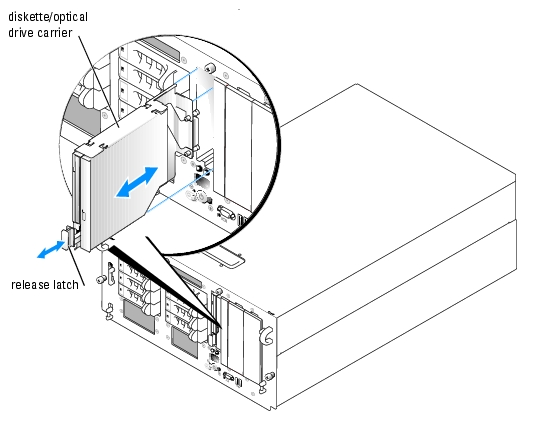
- To remove the drive carrier, pull the release latch forward, then slide the carrier out of the
chassis. See Figure 7-3.
Figure 7-3. Installing and Removing the Diskette/Optical Drive Carrier
- Remove the optical drive or optical drive filler plate from the carrier.
- Loosen the thumbscrew on the latch securing the optical drive or filler plate. See
Figure 7-4.
- Remove the latch.
- Lift the optical drive or optical drive filler plate from the carrier.
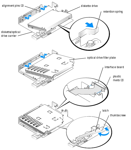
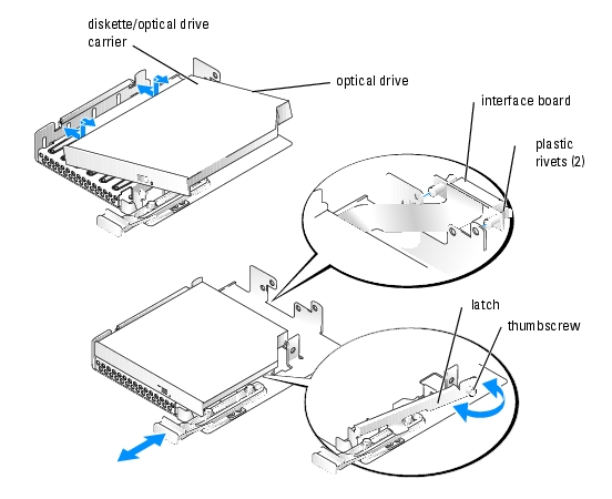
Figure 7-4. Installing a Diskette Drive in the Drive Carrier
- To remove the diskette drive filler plate, pull the retention spring slightly away from the filler
plate, then lift the filler plate from the carrier.
- Deflect the retention spring slightly, then insert the diskette drive into the carrier.
The pins on the carrier fit into the corresponding holes in the side of the drive. See Figure 7-3.
- Replace the optical drive or optical drive filler plate in the carrier.
The pins on the carrier fit into the corresponding holes in the side of the drive.
- Reinstall the latch and tighten the thumbscrew.
- Close the system. See "Closing the System" in "Troubleshooting Your System."
- Replace the front bezel, if it was removed in step 2. See "Closing the System" in
"Troubleshooting Your System."
- Reconnect the system and peripherals to their electrical outlets.
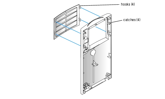
Removing the Peripheral Bay Filler Panel
(Tower Systems Only)
To facilitate access to optional drives in the peripheral bays, you can remove the peripheral bay filler panel from the system bezel.
- Remove the front bezel. See "Opening the System" in "Troubleshooting Your System."
- From the back of the bezel, press outwards on the four hooks securing the filler panel, then
remove the filler panel. See Figure 7-5.
Figure 7-5. Removing the Peripheral Bay Filler Panel from the Bezel
Installing an Optical Drive
|
|
CAUTION: Only trained service technicians are authorized to remove the system cover and access any of the components inside the system. See your Product Information Guide for complete information about safety precautions, working inside the computer, and protecting against electrostatic discharge. |
- Turn off the system, including any attached peripherals, and disconnect the system from the
electrical outlet.
- Remove the front bezel, if attached. See "Opening the System" in "Troubleshooting Your
System."
- Open the system. See "Opening the System" in "Troubleshooting Your System."
- To remove the drive carrier, pull the release latch forward, then slide the carrier out of the
chassis. See Figure 7-3.
- Remove the optical drive filler plate from the carrier.
- Loosen the thumbscrew from the latch securing the optical drive or filler plate. See
Figure 7-6.
- Remove the latch.
- Lift the optical drive filler plate from the carrier.
Figure 7-6. Installing an Optical Drive in the Drive Carrier
- Install the new optical drive in the carrier. See Figure 7-6.
The pins on the carrier fit into the corresponding holes in the side of the drive.
- Attach the interposer board to the back of the carrier, using the two plastic rivets. See
Figure 7-6.
- Reinstall the latch and tighten the thumbscrew.
- Close the system. See "Closing the System" in "Troubleshooting Your System."
- Replace the front bezel, if it was removed in step 2. See "Closing the System" in
"Troubleshooting Your System."
- Reconnect the system and peripherals to their electrical outlets.
Installing an Internal SCSI Tape Drive
This subsection describes how to configure and install an internal SCSI tape drive in the peripheral bays.
|
|
CAUTION: Only trained service technicians are authorized to remove the system cover and access any of the components inside the system. See your Product Information Guide for complete information about safety precautions, working inside the computer, and protecting against electrostatic discharge. |
- Turn off the system, including any attached peripherals, and disconnect the system from the
electrical outlet.
- Remove the front bezel, if attached. See "Opening the System" in "Troubleshooting Your
System."
- Open the system. See "Opening the System" in "Troubleshooting Your System."
- Ground yourself by touching an unpainted metal surface on the back of the system, unpack
the drive, and compare the jumper and switch settings with those in the documentation that
came with the drive.
- Unpack the tape drive (and controller card, if applicable) and configure the tape drive
according to the documentation that came with the tape drive, based on the following
guidelines:
- Each device attached to a SCSI host adapter must have a unique SCSI ID number.
(Narrow SCSI devices use IDs 0 to 7; wide SCSI devices use IDs from 0 to 15). Set the
drive's SCSI ID to avoid conflicts with other devices on the SCSI bus. For the default
SCSI ID setting, see the documentation provided with the drive.
|
|
NOTE: There is no requirement that SCSI ID numbers be assigned sequentially or that devices be attached to the cable in order by ID number. |
- SCSI logic requires that the two devices at opposite ends of a SCSI chain be terminated
and that all devices in between be unterminated. Therefore, you enable the tape drive's
termination if it is the last device in a chain of devices (or sole device) connected to the
SCSI controller.
- If a controller card was included in the drive kit, install the card now. See"Installing an
Expansion Card" in "Installing System Components."
- Remove the filler plate from the peripheral bay.
- If the mounting rails are not attached to the drive, install them now.
- Insert the drive into the peripheral bay.
- Connect the SCSI interface cable in the drive kit to the drive.
- Connect the drive to a SCSI controller:
- To use the system's intergrated SCSI controller, connect the SCSI interface cable to connector SCSI B on the riser card. See Figure A-4.
- If you are connecting the card to an optional SCSI controller card, connect the SCSI interface cable to the SCSI connector on the card.
- Connect the power cable supplied with the tape drive to the connector on the drive, and to
the power connector on the SCSI backplane. See Figure A-5.
- Close the system. See "Closing the System" in "Troubleshooting Your System."
- Replace the front bezel, if it was removed in step 2. See "Closing the System" in
"Troubleshooting Your System."
- Reconnect the system and peripherals to their electrical outlets, and turn them on.
- If you connected the drive to the integrated SCSI controller on the riser card, enter the
System Setup program.
From the Integrated Devices Screen, ensure that Channel B under the Embedded RAID Controller option is set to SCSI. See "Using the System Setup Program" in your User's Guide.
- Perform a tape backup and verification test with the drive as instructed in the software
documentation that came with the drive.
Connecting an External SCSI Tape Drive
This subsection describes how to configure and install an external SCSI tape drive. The drive may be connected to the integrated SCSI controller using the SCSI connector on the system back panel, or to an optional SCSI controller card.
|
|
CAUTION: Only trained service technicians are authorized to remove the system cover and access any of the components inside the system. See your Product Information Guide for complete information about safety precautions, working inside the computer, and protecting against electrostatic discharge. |
- Turn off the system, including any attached peripherals, and disconnect the system from the
electrical outlet.
- Remove the front bezel, if attached. See "Opening the System" in "Troubleshooting Your
System."
- Open the system. See "Opening the System" in "Troubleshooting Your System."
- Ground yourself by touching an unpainted metal surface on the back of the system, unpack
the drive, and compare the jumper and switch settings with those in the documentation that
came with the drive.
- Unpack the tape drive (and controller card, if applicable) and configure the tape drive
according to the documentation that came with the tape drive, based on the following
guidelines:
- Each device attached to a SCSI host adapter must have a unique SCSI ID number.
(Narrow SCSI devices use IDs 0 to 7; wide SCSI devices use IDs from 0 to 15). Set the
drive's SCSI ID to avoid conflicts with other devices on the SCSI bus. For the default
SCSI ID setting, see the documentation provided with the drive.
|
|
NOTE: There is no requirement that SCSI ID numbers be assigned sequentially or that devices be attached to the cable in order by ID number. |
- SCSI logic requires that the two devices at opposite ends of a SCSI chain be terminated
and that all devices in between be unterminated. Therefore, you enable the tape drive's
termination if it is the last device in a chain of devices (or sole device) connected to the
SCSI controller.
- If you are connecting the drive to a controller card, install the controller card in an expansion
slot. See "Installing an Expansion Card" in "Installing System Components."
- Connect the tape drive's SCSI interface cable to the drive.
- Connect the other end of the SCSI interface cable to the SCSI controller card, or the external
SCSI connector on the system's back panel (see Figure 2-2).
- Connect the tape drive's power cable to an electrical outlet.
- Close the system. See "Closing the System" in "Troubleshooting Your System."
- Replace the front bezel, if it was removed in step 2. See "Closing the System" in
"Troubleshooting Your System."
- Reconnect the system and peripherals to their electrical outlets, and turn them on.
- Perform a tape backup and verification test with the drive as instructed in the software
documentation that came with the drive.
Configuring the Boot Drive
The drive or device from which the system boots is determined by the boot order specified in the System Setup program. See "Using the System Setup Program" in your User's Guide.
Activating the Optional Integrated RAID Controller
This subsection explains how to activate your system's integrated RAID controller.
|
|
CAUTION: Only trained service technicians are authorized to remove the system cover and access any of the components inside the system. See your Product Information Guide for complete information about safety precautions, working inside the computer, and protecting against electrostatic discharge. |
|
|
CAUTION: Replace the battery only with the same or equivalent type recommended by the manufacturer. Discard used batteries according to the manufacturer's instructions. See your Product Information Guide for additional information. |
|
|
NOTICE: To avoid possible data loss, back up all data on the hard drives before changing the mode of operation of the integrated SCSI controller from SCSI to RAID. |
- Turn off the system, including any attached peripherals, and disconnect the system from the
electrical outlet.
- Remove the cover. See "Opening the System."
- Remove the memory cooling shroud by lifting the release latch and sliding the shroud
forward. See Figure 6-16.
- Insert the RAID hardware key into its connector on the system board and secure the key with
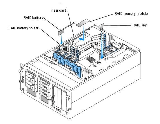
the latches on each end of the connector. See Figure 7-7 and Figure A-3.
Figure 7-7. Activating the Integrated RAID Controller
- Locate the RAID memory module connector on the riser card. See Figure 7-7.
- Push the ejectors on the RAID memory module connector outward to allow the memory
module to be inserted into the connector.
- Align the RAID memory module's edge connector with the alignment keys, and insert the
memory module into the connector.
|
|
NOTE: Do not substitute registered memory modules such as those used for system memory. Use the memory module supplied in the RAID upgrade kit. |
- Press on the memory module with your thumbs while closing the ejectors with your index
fingers to lock the memory module into the connector.
- Insert the RAID battery into the battery holder. See Figure 7-7.
- Thread the battery power cable through the hole in the back of the battery holder.
- Connect the battery power cable to the RAID battery cable connector on the riser card. See
Figure A-4.
- Replace the memory cooling shroud.
- Replace the cover. See "Closing the System."
- Reconnect the system to its electrical outlet and turn the system on, including any attached
peripherals.
- Enter the System Setup program and verify that the setting for the SCSI controller has
changed to reflect the presence of the RAID hardware. See "Using the System Setup Program"
in your User's Guide.
- Install and configure the RAID software.
See the RAID software documentation for more information.
Installing a RAID Controller Card
See "Installing an Expansion Card" in "Installing System Components" for instructions about installing the card. See the RAID controller documentation for information on installing and configuring the RAID software.
SCSI Hard-Drive Cabling Guidelines
Non-RAID Configurations
For a system without an optional RAID controller installed, connect SCSI channel A on the riser card to connector SCSIA on the SCSI backplane board. If the optional external SCSI cable is installed, connect it to SCSI channel B on the riser card.
RAID Configurations
If the optional ROMB controller is enabled, or an optional RAID controller card is installed, you can configure the hard drives for RAID operation. The general cabling configurations for various system options are discussed in the following subsections. For details on drive requirements for specific RAID types, see your RAID controller documentation.
1x8 Drive Configuration
For a 1x8 drive configuration with no optional 1x2 backplane installed in the system, connect SCSI channel A on the riser card (see Figure A-4) or SCSI channel A on the optional RAID card to connector SCSIA on the 1x8 backplane (see Figure A-5). Drive 0 functions as the boot drive.
1x8 plus 1x2 Drive Configuration
If an optional 1x2 backplane is installed in the peripheral bay, follow these guidelines:
- Connect the 1x2 backplane to SCSI channel A on the riser card (see Figure A-4) or SCSI channel A on the optional RAID controller card. Drive 0 in the 1x2 drive cage functions as the boot drive.
- Connect a SCSI cable from connector SCSIA on the 1x8 backplane (see Figure A-5)to SCSI channel B on the riser card (see Figure A-5) or channel B of the optional RAID controller card.
2x4 Split Backplane Configurations
|
|
NOTICE: An optional daughter card must be installed on the back of the 1x8 SCSI backplane to support split 2x4 backplane operation. |
- To use the optional integrated ROMB controller in a split 2x4 backplane configuration:
- Connect SCSI channel A on the riser card (see Figure A-4) to connector SCSIA on the SCSI backplane (see Figure A-5). This channel controls the boot drive (drive 0) and drives 1, 2, and 3.
- Connect SCSI channel B on the riser card (see Figure A-4) to connector SCSIB on the SCSI backplane (see Figure A-5). This channel controls drives 4 through 7.
- To use an optional RAID controller card in a split 2x4 backplane configuration:
- Connect SCSI channel A (channel 0) on the controller card to connector SCSIA on the SCSI backplane (see Figure A-5). This channel controls the boot drive (drive 0) and drives 1, 2, and 3.
- Connect SCSI channel B (channel 1) on the controller card to connector SCSIB on the SCSI backplane (see Figure A-5). This channel controls drives 4, 5, 7, and 9.
Back to Contents Page