Back to Contents Page
Installing System Components
Dell™ PowerEdge™ 2800 Systems Installation and Troubleshooting Guide
 System Board Components
System Battery
Fans
Power Supplies
Expansion Cards
System Memory
Processor
Installing a RAC Card
This section describes how to install the following system components:
- System battery
- Cooling fans
- Power supplies
- Expansion cards
- Riser card
- System memory
- Processors
- RAC card
For information on adding SCSI devices, other types of drives, or activating the optional integrated RAID controller, see "Installing Drives."
System Board Components
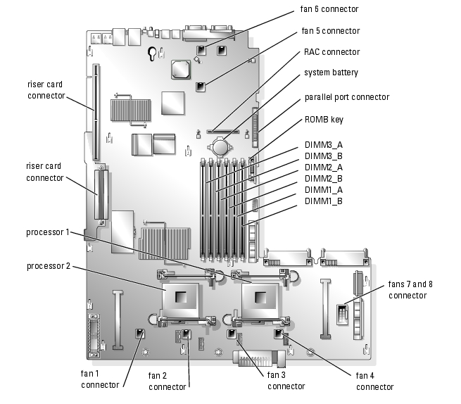
When installing and replacing system board components, use Figure 6-1 to locate the components.
Figure 6-1. System Board Components and Connectors
System Battery
Replacing the System Battery

|
CAUTION: Only trained service technicians are authorized to remove the system cover and access any of the components inside the system. See your Product Information Guide for complete information about safety precautions, working inside the computer, and protecting against electrostatic discharge. |
- Enter the System Setup program and record the option settings on the System Setup screens.
See "Using the System Setup Program" in the User's Guide.
- Open the system. See "Opening the System" in "Troubleshooting Your System."
- Remove the memory cooling shroud by lifting the release latch and sliding the shroud
forward. See Figure 6-16.
- Remove the system battery. See Figure A-3 for the battery connector location on the system
board.

|
NOTICE: To avoid damage to the battery connector, you must firmly support the connector while installing or removing a battery. |
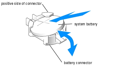
- Support the battery connector by pressing down firmly on the positive side of the
connector. See Figure 6-2.
- While supporting the battery connector, press the battery toward the positive side of the
connector and pry it up out of the securing tabs at the negative side of the connector.
Figure 6-2. Replacing the System Battery
- Install the new system battery with the side labeled "+" facing up. See Figure 6-2.

|
NOTE: The side of the battery labeled "+" must face toward the open side of the battery socket. |
- Install the new system battery.
- Support the battery connector by pressing down firmly on the positive side of the
connector.
- Hold the battery with the "+" facing up, and slide it under the securing tabs at the
positive side of the connector.
- Press the battery straight down into the connector until it snaps into place.
- Replace the memory cooling shroud.
- Close the system. See "Closing the System" in "Troubleshooting Your System."
- Enter the System Setup program to confirm that the battery operates properly.
- From the main screen, select System Time to enter the correct time and date.
- Re-enter any system configuration information that is no longer displayed on the System
Setup screens, and then exit the System Setup program.
- To test the newly installed battery, see "Troubleshooting the System Battery" in
"Troubleshooting Your System."
Fans
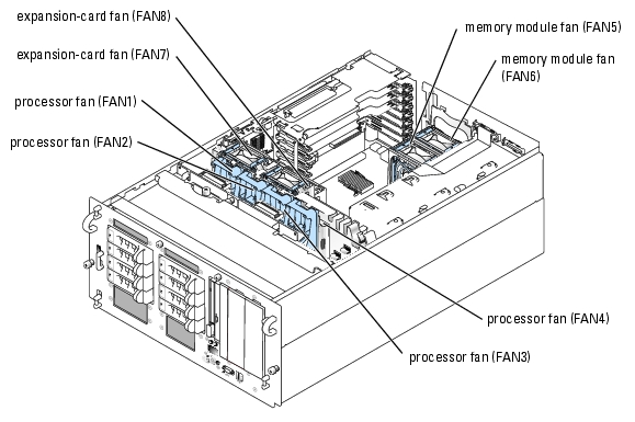
The system's eight hot-plug fans provide cooling for the processors, memory modules, and expansion cards (see Figure 6-3.)
- Two processor cooling fans for each processor installed in the system (fans 1 through 4)
- Two memory module cooling fans (fan 5 and fan 6)
- Two expansion-card cooling fans (fan 7 and fan 8)
|
|
NOTICE: In the event of a problem with a particular fan, the fan's number is referenced by the system's management software, allowing you to easily identify and replace the proper fan. |
Figure 6-3. Cooling Fans
Removing a Processor Fan
|
|
CAUTION: Only trained service technicians are authorized to remove the system cover and access any of the components inside the system. See your Product Information Guide for complete information about safety precautions, working inside the computer, and protecting against electrostatic discharge. |
- Open the system. See "Opening the System" in "Troubleshooting Your System."
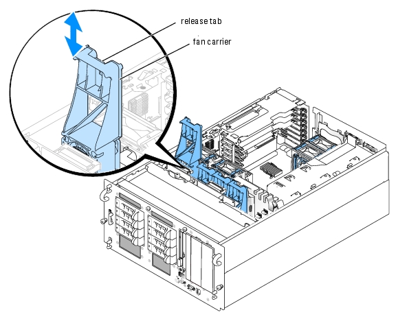
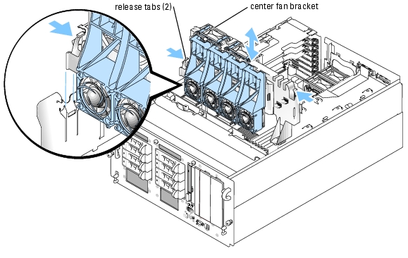
- Press the release tab on the fan carrier and lift the fan out of the center fan bracket. See
Figure 6-4.
Figure 6-4. Installing and Removing a Processor Fan
Removing the Center Fan Bracket
|
|
CAUTION: Only trained service technicians are authorized to remove the system cover and access any of the components inside the system. See your Product Information Guide for complete information about safety precautions, working inside the computer, and protecting against electrostatic discharge. |
- Open the system. See "Opening the System" in "Troubleshooting Your System."
- Remove the processor fans and expansion card fans. See "Removing a Processor Fan" and
"Removing an Expansion-Card Fan."
- Remove the expansion-card cage. See "Removing the Expansion-Card Cage."
- Press the release tab on each end of the center fan bracket, then slide the bracket straight up
and out of the system. See Figure 6-5.
|
|
NOTE: When reinstalling the center fan bracket, ensure that the power connector on the bracket is aligned with the corresponding connector on the system board. |
Figure 6-5. Installing and Removing the Center Fan Bracket
Replacing the Center Fan Bracket
- Slide the bracket into the system. Ensure that the power connector on the bracket is aligned
with the corresponding connector on the system board.
- Reinstall the expansion-card cage. See "Installing the Expansion-Card Cage."
- Replace the processor fans and expansion-card fans.
Removing a Memory Module Fan
|
|
CAUTION: Only trained service technicians are authorized to remove the system cover and access any of the components inside the system. See your Product Information Guide for complete information about safety precautions, working inside the computer, and protecting against electrostatic discharge. |
- Open the system. See "Opening the System" in "Troubleshooting Your System."
- Compress the two latches on the top of the fan, then remove the fan. See Figure 6-6.
Figure 6-6. Installing and Removing a Memory Module Fan
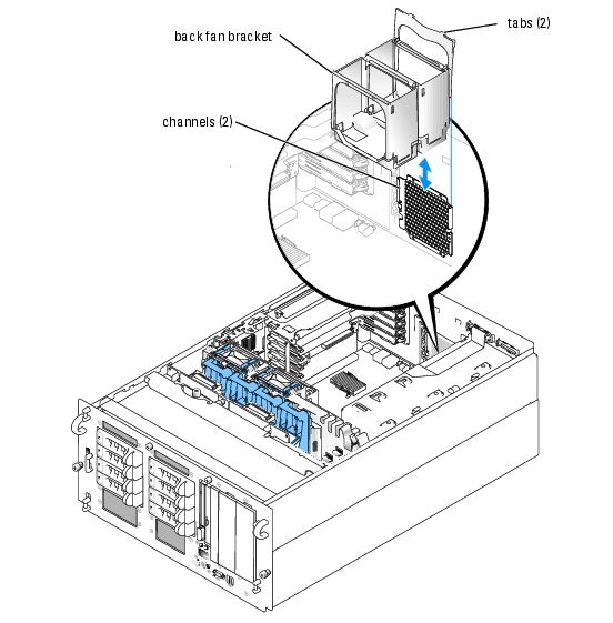
Removing and Replacing the Back Fan Bracket
To remove the back fan bracket, pull the upper edge of the bracket away from the system back panel, then slide the bracket upwards. See Figure 6-7.
Figure 6-7. Removing and Replacing the Back Fan Bracket
Replacing the Back Fan Bracket
- Slide the left and right edges of the bracket into the two corresponding channels on the inside
of the system chassis back panel. See Figure 6-7.
- Lower the bracket into the system until the two tabs on the top edge of the bracket fit into
the slots in the system back panel.
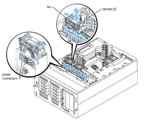
Removing an Expansion-Card Fan
|
|
CAUTION: Only trained service technicians are authorized to remove the system cover and access any of the components inside the system. See your Product Information Guide for complete information about safety precautions, working inside the computer, and protecting against electrostatic discharge. |
- Open the system. See "Opening the System" in "Troubleshooting Your System."
- Compress the two latches on the top of the fan, then remove the fan. See Figure 6-8.
When installing the fan, ensure that the power connector on the fan is aligned with the connector on the center fan bracket. See Figure 6-8.
Figure 6-8. Installing and Removing an Expansion-Card Fan
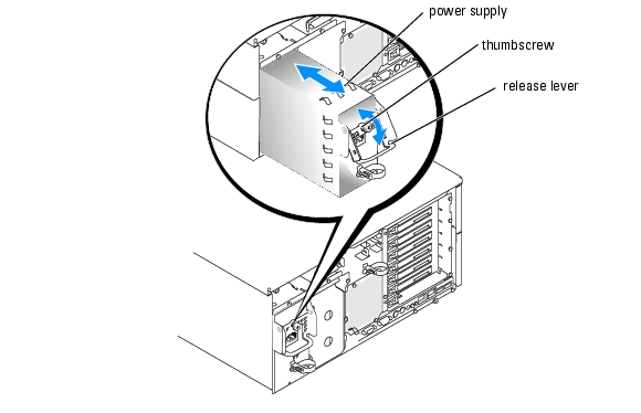
Power Supplies
Removing a Power Supply
|
|
NOTICE: The system requires one power supply for the system to operate normally. The system is in the redundant mode when two power supplies are installed and both power supplies are connected to an AC power source. Remove and replace only one power supply at a time in a system that is powered on. |
|
|
NOTICE: If only one power supply is installed, it must be installed in the left power supply bay (1). |
- Disconnect the power cable from the power source.
- Disconnect the power cable from the power supply.
- Loosen the thumbscrew on the release lever, then open the lever and slide the power supply
out of the chassis. See Figure 6-9.
Figure 6-9. Installing and Removing a Power Supply
Installing a Power Supply
- If you are adding a second power supply, remove the power supply filler panel. See "Removing
the Power Supply Bay Filler Panel."
- Holding the release lever in the open position, slide the new power supply into the chassis
until the release lever contacts the system chassis. See Figure 6-9.
- Close the release lever until the power supply is fully seated.
- Lock the retention lever in place using the thumbscrew. See Figure 6-9.
- Connect the power cable to the power supply and plug the cable into a power outlet.
|
|
NOTICE: When connecting the power cable, insert the cable through the strain-relief loop. |
After installing a new power supply in a system with two power supplies, allow several seconds for the system to recognize the power supply and determine whether it is working properly. The power-on indicator will turn green to signify that the power supply is functioning properly (see Figure 2-4).
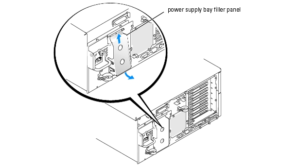
Removing the Power Supply Bay Filler Panel
- Grasp the filler panel using the two holes. See Figure 6-10.
- Lift the panel upwards, then rotate the lower edge of the panel away from the system back
panel. See Figure 6-10.
Figure 6-10. Removing the Power Supply Bay Filler Panel
Expansion Cards
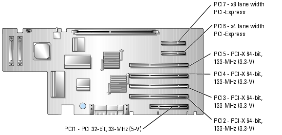
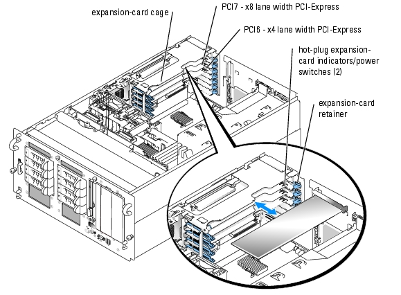
Your system supports up to seven full-length expansion cards, installed in connectors on a riser card. The expansion slots are configured as follows:
- Slot 1 is a 5-V, 32-bit, 33-MHz legacy PCI expansion slot.
- Slots 2 through 5 are 3.3-V, 64-bit, 133-MHz PCI-X expansion slots.
- Slot 6 is a hot-plug, x4 lane-width PCI-Express expansion slot.
- Slot 7 is a hot-plug, x8 lane-width PCI-Express expansion slot.
Figure 6-11 shows the relative locations of the expansion-card slots
Figure 6-11. Expansion Slots
Hot-Plug Expansion Cards
Your system supports PCI Express hot-plug expansion cards in slots 6 and 7. The indicators on each expansion slot insulator show the state of the expansion-card connector. See Figure 6-11 and Table 6-1.
|
|
NOTICE: Your system's operating system and the expansion card itself must both support hot-plug installation and removal. |
|
|
NOTICE: To avoid damage to the expansion card or system board, refer to the expansion slot indicator when you add or remove a PCI-Express expansion card. |
Table 6-1. Hot-Plug Expansion Slot Indicators
|
Green Power Indicator
|
Amber Attention Indicator
|
Safe to Add / Remove Card
|
Description
|
|---|
Off
| Off
| Yes
| Connector power is off
|
On
| Off
| No
| Connector power is on
|
Flash
| Off
| No
| Connector is being powered up or powered down
|
Off
| On
| Yes
| Fault
|
On
| Flash
| No
| Slot is being identified
|
Removing the Expansion-Card Cage
To install non-hot plug expansion cards or access certain system components such as the processors, you must remove the expansion-card cage.
|
|
NOTE: You should not remove the expansion-card cage in order to install or remove hot-plug expansion cards. |
|
|
CAUTION: Only trained service technicians are authorized to remove the system cover and access any of the components inside the system. See your Product Information Guide for complete information about safety precautions, working inside the computer, and protecting against electrostatic discharge. |
- Turn off the system and attached peripherals, and disconnect the system from the electrical
outlet.
- Open the system. See "Opening the System" in "Troubleshooting Your System."
|
|
NOTICE: If two SCSI data cables are connected to the riser card, carefully note their relative locations so you can reinstall them correctly. |
- Disconnect the SCSI data cable(s) from the riser card.
If two SCSI cables are connected, note their relative locations.
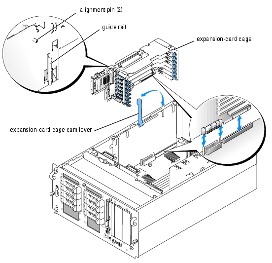
- Unlock the expansion-card cage cam lever and rotate it to the vertical position. See
Figure 6-12.
- Lift the expansion-card cage from the chassis.
Figure 6-12. Installing and Removing the Expansion-Card Cage
Installing the Expansion-Card Cage
|
|
CAUTION: Only trained service technicians are authorized to remove the system cover and access any of the components inside the system. See your Product Information Guide for complete information about safety precautions, working inside the computer, and protecting against electrostatic discharge. |
- Reinstall any expansion card(s). See "Installing an Expansion Card."
- Raise the expansion-card cage cam lever to a vertical position. See Figure 6-12.
- Fit the guide rail on the back of the expansion-card cage into the corresponding notch in the
system chassis, then lower the expansion-card cage into the system chassis. See Figure 6-12.
- As you lower the cage into place, the two alignment pins fit into the slots in the side of the
system.
- Carefully close the cam lever to lock the card cage into place.
|
|
NOTICE: If two SCSI data cables were connected to the riser card or SCSI controller, reinstall them in the same relative locations. |
- Reconnect the SCSI data cable(s) to the SCSI connector(s) on the riser card or SCSI
controller. SeeFigure A-4.
- Close the system. See "Closing the System" in "Troubleshooting Your System."
Installing an Expansion Card
|
|
CAUTION: Only trained service technicians are authorized to remove the system cover and access any of the components inside the system. See your Product Information Guide for complete information about safety precautions, working inside the computer, and protecting against electrostatic discharge. |
Installing a Non-Hot-Plug Expansion Card
- Turn off the system and attached peripherals, and disconnect the system from the electrical
outlet.
- Open the system. See "Opening the System" in "Troubleshooting Your System."
- Remove the expansion-card cage. See "Removing the Expansion-Card Cage."
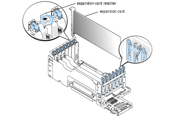
- Open the plastic expansion-card retainer adjacent to the back of the empty slot. See
Figure 6-13.
Figure 6-13. Installing and Removing Non-Hot-Plug Expansion Cards
- Remove the filler bracket on the slot you will be using.
|
|
NOTE: Keep this bracket if you need to remove the expansion card. Filler brackets must be installed over empty expansion-card slots to maintain Federal Communications Commission (FCC) certification of the system. The brackets also keep dust and dirt out of the system and aid in proper cooling and airflow inside the system. |
- Insert the expansion card firmly into the expansion-card connector until the card is fully
seated.
|
|
NOTE: Ensure that the expansion-card bracket is also inserted into the securing slot on the back of the expansion-card cage. |
- Close the expansion-card retainer. See Figure 6-13.
- Reinstall the expansion-card cage. See "Installing the Expansion-Card Cage."
- Connect any internal or external cable(s) to the expansion card.
- Close the system. See "Closing the System" in "Troubleshooting Your System."
Installing a Hot-Plug Expansion Card
|
|
NOTICE: Your system's operating system and the expansion card itself must both support hot-plug installation and removal. |
- Open the system. See "Opening the System" in "Troubleshooting Your System."
- To power down the expansion slot, press the indicator/switch at the end of the expansion slot.
See Figure 6-14
- Wait until the green and amber indicators for the slot are both off. See Figure 6-14 and
Table 6-1.
Figure 6-14. Installing and Removing Hot-Plug Expansion Cards
- Open the plastic expansion-card retainer adjacent to the back of the empty slot. See
Figure 6-14.
- Remove the filler bracket on the slot you will be using.
|
|
NOTICE: Be very careful when removing the bracket to avoid dropping it onto the system board and damaging the system board. |
|
|
NOTE: Keep this bracket if you need to remove the expansion card. Filler brackets must be installed over empty expansion-card slots to maintain FCC certification of the system. The brackets also keep dust and dirt out of the system and aid in proper cooling and airflow inside the system. |
- Insert the expansion card firmly into the expansion-card connector until the card is fully
seated, being careful not to remove the riser card from the system board. Ensure that the
expansion-card bracket is also inserted into the securing slot on the chassis's back panel.
- Close the expansion-card retainer.
- Connect any internal or external cable(s) to the expansion card.
- Power up the expansion slot.
- Close the system. See "Closing the System" in "Troubleshooting Your System."
Removing an Expansion Card
Removing a Non-Hot Plug Expansion Card
|
|
CAUTION: See your Product Information Guide for complete information about safety precautions, working inside the computer, and protecting against electrostatic discharge. |
- Turn off the system and attached peripherals, and disconnect the system from the electrical
outlet.
- Open the system. See "Opening the System" in "Troubleshooting Your System."
- Disconnect any internal or external cable(s) that are connected to the expansion card.
- Remove the expansion-card cage. See "Removing the Expansion-Card Cage."
- Open the expansion-card retainer adjacent to the slot. See Figure 6-13.
- Grasp the expansion card and carefully remove it from the riser-card connector.
- If you are permanently removing the card, replace the metal filler bracket over the empty
card-slot opening.
|
|
NOTE: Filler brackets must be installed over empty expansion-card slots to maintain FCC certification of the system. The brackets also keep dust and dirt out of the system and aid in proper cooling and airflow inside the system. |
- Close the expansion-card retainer.
- Reinstall the expansion-card cage. See "Installing the Expansion-Card Cage."
- Close the system. See "Closing the System" in "Troubleshooting Your System."
Removing a Hot-Plug Expansion Card
|
|
CAUTION: See your Product Information Guide for complete information about safety precautions, working inside the computer, and protecting against electrostatic discharge. |
- Open the system. See "Opening the System" in "Troubleshooting Your System."
- To power down the expansion slot, press the indicator/switch at the end of the expansion slot.
See Figure 6-14.
- Wait until the green and amber indicators for the slot are both off. See Figure 6-14 and
Table 6-1.
- Disconnect any internal or external cable(s) that are connected to the expansion card.
- Open the expansion-card retainer adjacent to the PCI slot.
- Grasp the expansion card and carefully remove it from the riser-card connector.
- If you are permanently removing the card, replace the metal filler bracket over the empty
card-slot opening.
|
|
NOTE: Filler brackets must be installed over empty expansion-card slots to maintain FCC certification of the system. The brackets also keep dust and dirt out of the system and aid in proper cooling and airflow inside the system. |
- Close the expansion-card retainer.
- Close the system. See "Closing the System" in "Troubleshooting Your System."
System Memory
You can upgrade your system memory to a maximum of 16 GB by installing combinations of 256-MB, 512-MB, 1-GB, 2-GB, or 4-GB (when available) 2-way registered ECC PC2-3200 (DDR II 400) memory. The memory sockets are located on the system board adjacent to the power supply bays. See Figure 6-1.
|
|
NOTE: Two-way interleaving is not supported in the 256-MB single memory module configuration. |
|
|
NOTICE: If you remove your original memory modules from the system during a memory upgrade, keep them separate from any new memory modules that you may have. Use only registered ECC PC2-3200 compliant (DDR II 400) memory modules. |
The system memory is located on the system board adjacent to the power supply bays. See Figure 6-1. The memory module sockets are arranged in three banks on two channels (A and B). The memory module banks are identified as follows:
- Bank 1: DIMM1_A and DIMM1_B
- Bank 2: DIMM2_A and DIMM2_B
- Bank 3: DIMM3_A and DIMM3_B
General Memory Module Installation Guidelines
- If only one memory module is installed, it must be installed in socket DIMM1_A or DIMM1_B.
- If two or more memory modules are installed, they must be installed in pairs of matched memory size, speed, and technology.
- The system supports both single-ranked and dual-ranked memory modules.
- If you install both single-ranked and dual-ranked memory modules, the dual-ranked memory modules must be installed in bank 1.
- Dual-ranked memory modules are not supported in bank 3.
- If dual-ranked memory modules are installed in bank 2, you cannot install any memory modules in bank 3.
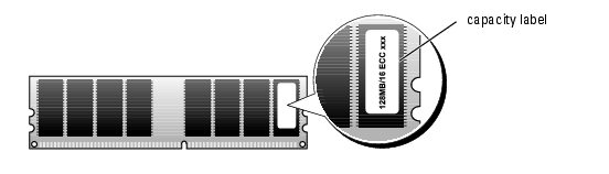
Memory modules marked with a 1R are single ranked and modules marked with a 2R are dual ranked. See Figure 6-15.
Figure 6-15. Determining a Memory Module's Capacity and Rank
Spare Bank Support
If six identical single-rank memory modules are installed, the memory modules in bank 3 (DIMM3_A and DIMM3_B) can function as a spare bank if you select the spare bank option using the System Setup program.
Memory Mirroring Support
The system supports memory mirroring if identical memory modules are installed in bank 1 and bank 2, and no memory modules are installed in bank 3.
Table 6-2 and Table 6-3 show examples of different memory configurations. Table 6-3 lists the various allowable combinations of single- and dual-ranked memory modules
Table 6-2. Sample Memory Configurations
|
Total Memory
|
DIMM1_A
|
DIMM1_B
|
DIMM2_A
|
DIMM2_B
|
DIMM3_A
|
DIMM3_B
|
|---|
256 MB
| 256 MB
| none
| none
| none
| none
| none
|
1 GB
| 256 MB
| 256 MB
| 256 MB
| 256 MB
| none
| none
|
1 GB
| 512 MB
| 512 MB
| none
| none
| none
| none
|
2 GB
| 512 MB
| 512 MB
| 512 MB
| 512 MB
| none
| none
|
2 GB
| 1 GB
| 1 GB
| none
| none
| none
| none
|
3 GB
| 1 GB
| 1 GB
| 512 MB
| 512 MB
| none
| none
|
3 GB
| 512 MB
| 512 MB
| 512 MB
| 512 MB
| 512 MB
| 512 MB
|
4 GB
| 1 GB
| 1 GB
| 1 GB
| 1 GB
| none
| none
|
4 GB
| 1 GB
| 1 GB
| 512 MB
| 512 MB
| 512 MB
| 512 MB
|
6 GB
| 2 GB
| 2 GB
| 1 GB
| 1 GB
| none
| none
|
6 GB
| 1 GB
| 1 GB
| 1 GB
| 1 GB
| 1 GB
| 1 GB
|
8 GB
| 2 GB
| 2 GB
| 2 GB
| 2 GB
| none
| none
|
8 GB
| 4 GB
| 4 GB
| none
| none
| none
| none
|
12 GB
| 2 GB
| 2 GB
| 2 GB
| 2 GB
| 2 GB
| 2 GB
|
16 GB
| 4 GB
| 4 GB
| 4 GB
| 4 GB
| none
| none
|
Table 6-3. Allowable Memory Module Configurations – Single-Ranked and Dual-Ranked Memory Modules
|
DIMM1_A
|
DIMM1_B
|
DIMM2_A
|
DIMM2_B
|
DIMM3_A
|
DIMM3_B
|
|---|
Single rank
| none
| none
| none
| none
| none
|
Single rank
| Single rank
| none
| none
| none
| none
|
Dual rank
| Dual rank
| none
| none
| none
| none
|
Single rank
| Single rank
| Single rank
| Single rank
| none
| none
|
Dual rank
| Dual rank
| Dual rank
| Dual rank
| none
| none
|
Dual rank
| Dual rank
| Single rank
| Single rank
| none
| none
|
Single rank
| Single rank
| Single rank
| Single rank
| Single rank
| Single rank
|
Dual rank
| Dual rank
| Single rank
| Single rank
| Single rank
| Single rank
|
Installing Memory Modules
|
|
CAUTION: Only trained service technicians are authorized to remove the system cover and access any of the components inside the system. See your Product Information Guide for complete information about safety precautions, working inside the computer, and protecting against electrostatic discharge. |
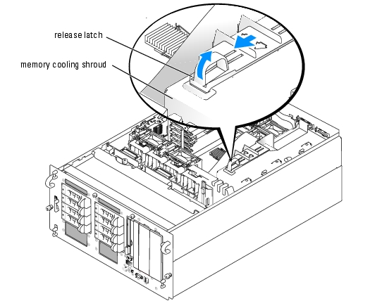
- Open the system. See "Opening the System" in "Troubleshooting Your System."
- To remove the memory cooling shroud, lift the release latch and slide the shroud forward. See
Figure 6-16.
Figure 6-16. Removing the Memory Cooling Shroud
- Locate the memory module sockets. See Figure A-3.
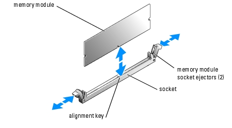
- Press the ejectors on the memory module socket down and out, as shown in Figure 6-17, to
allow the memory module to be inserted into the socket.
Figure 6-17. Installing and Removing a Memory Module
- Align the memory module's edge connector with the alignment key on the memory module
socket, and insert the memory module in the socket.
|
|
NOTE: The memory module socket has an alignment key that allows you to install the memory module in the socket in only one way. |
- Press down on the memory module with your thumbs while pulling up on the ejectors with
your index fingers to lock the memory module into the socket.
When the memory module is properly seated in the socket, the ejectors on the memory module socket align with the ejectors on the other sockets that have memory modules installed.
- Repeat step 3 through step 6 of this procedure to install the remaining memory modules. See
Table 6-2 and Table 6-3 for sample memory configurations.
- Replace the memory cooling shroud.
- Close the system. See "Closing the System" in "Troubleshooting Your System."
- (Optional) Press <F2> to enter the System Setup program, and check the System Memory
setting on the main System Setup screen.
The system should have already changed the value to reflect the newly installed memory.
- If the value is incorrect, one or more of the memory modules may not be installed properly.
Repeat step 1 through step 10 of this procedure, checking to ensure that the memory modules
are firmly seated in their sockets.
- Run the system memory test in the system diagnostics. See "Running the System
Diagnostics."
Removing Memory Modules
|
|
CAUTION: Only trained service technicians are authorized to remove the system cover and access any of the components inside the system. See your Product Information Guide for complete information about safety precautions, working inside the computer, and protecting against electrostatic discharge. |
- Open the system. See "Opening the System" in "Troubleshooting Your System."
- Locate the memory module sockets. See Figure 6-1.
- Press down and out on the ejectors on each end of the socket until the memory module pops
out of the socket. See Figure 6-17.
- Close the system. See "Closing the System" in "Troubleshooting Your System."
Processor
You can upgrade the system processor(s) to take advantage of future options in speed and functionality, or add a second processor. Each processor and its associated internal cache memory are contained in a pin grid array (PGA) package that is installed in a ZIF socket on the system board.
The following items are included in the processor upgrade kit:
- Processor
- Heat sink
- Two processor cooling fans (if you are adding a second processor)
Replacing a Processor
|
|
CAUTION: Only trained service technicians are authorized to remove the system cover and access any of the components inside the system. See your Product Information Guide for complete information about safety precautions, working inside the computer, and protecting against electrostatic discharge. |
- Open the system. See "Opening the System" in "Troubleshooting Your System."
- Remove the center fan bracket. See "Removing the Center Fan Bracket."
|
|
NOTICE: When you remove the heat sink, the possibility exists that the processor might adhere to the heat sink and be removed from the socket. It is recommended that you remove the heat sink while the processor is still warm. |
|
|
NOTICE: Never remove the heat sink from a processor unless you intend to remove the processor. The heat sink is necessary to maintain proper thermal conditions. |
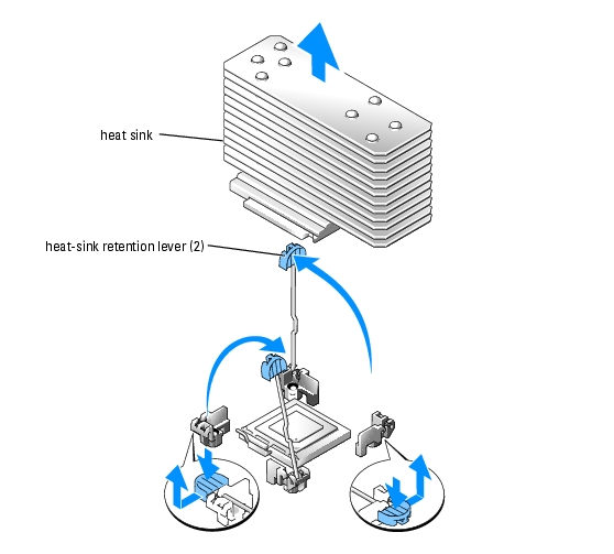
- Press the blue tab on the end of one of the heat-sink retention levers to disengage the lever,
then lift the lever 90 degrees. See Figure 6-18.
Figure 6-18. Installing and Removing the Heat Sink
- Wait 30 seconds for the heat sink to loosen from the processor.
- Open the other heat sink retention lever.
- If the heat sink has not separated from the processor, carefully rotate the heat sink in a
clockwise, then counterclockwise, direction until it releases from the processor. Do not pry the
heat sink off of the processor.
- Lift the heat sink off of the processor and set the heat sink upside down so as not to
contaminate the thermal grease.
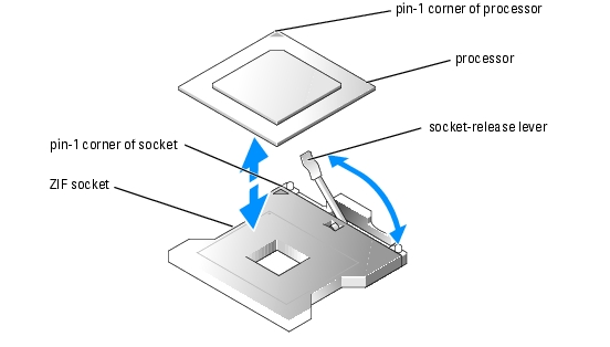
- Pull the socket-release lever straight up until the processor is released from the socket. See
Figure 6-19.
Figure 6-19. Installing and Removing a Processor
- Lift the processor out of the socket and leave the release lever up so that the socket is ready for
the new processor.
|
|
NOTICE: Be careful not to bend any of the pins when removing the processor. Bending the pins can permanently damage the processor. |
- Unpack the new processor.
If any of the pins on the processor appear bent, see "Getting Help."
- Align the pin-1 corner of the processor with the pin-1 corner of the ZIF socket. See
Figure 6-19.
|
|
NOTE: Identifying the pin-1 corners is critical to positioning the processor correctly. |
Identify the pin-1 corner of the processor by locating the tiny gold triangle on one corner of the processor. Place this corner in the same corner of the ZIF socket identified by a corresponding triangle.
- Install the processor in the socket.
|
|
NOTICE: Positioning the processor incorrectly can permanently damage the processor and the system when you turn it on. When placing the processor in the socket, be sure that all of the pins on the processor enter the corresponding holes. Be careful not to bend the pins. |
- If the release lever on the processor socket is not positioned all the way up, move it to that
position.
- With the pin-1 corners of the processor and socket aligned, set the processor lightly in the
socket, making sure all pins are matched with the correct holes in the socket.
Because the system uses a ZIF processor socket, do not use force, which could bend the pins if the processor is misaligned.
When the processor is positioned correctly, it drops down into the socket with minimal pressure.
- When the processor is fully seated in the socket, rotate the socket release lever back down
until it snaps into place, securing the processor.
- Install the heat sink.
- Using a clean lint-free cloth, remove the existing thermal grease from the heat sink.
|
|
NOTE: Use the heat sink that you removed in step 7. |
- Apply thermal grease evenly to the top of the processor.
- Place the heat sink onto the processor. See Figure 6-18.
- Close one of the two heat sink retention levers until it locks. See Figure 6-18.
- Repeat for the other heat sink retention lever.
- Reinstall the center fan bracket. See "Replacing the Center Fan Bracket."
- If you have added a second processor, install the two processor cooling fans for the new
processor. See "Installing and Removing a Processor Fan."
- Close the system. See "Closing the System" in "Troubleshooting Your System."
As the system boots, it detects the presence of the new processor and automatically changes the system configuration information in the System Setup program.
- Press <F2> to enter the System Setup program, and check that the processor information
matches the new system configuration.
See your User's Guide for instructions about using the System Setup program.
- Run the system diagnostics to verify that the new processor operates correctly.
See "Running the System Diagnostics" for information about running the diagnostics and troubleshooting processor problems.
Installing a RAC Card
|
|
CAUTION: Only trained service technicians are authorized to remove the system cover and access any of the components inside the system. See your Product Information Guide for complete information about safety precautions, working inside the computer, and protecting against electrostatic discharge. |
- Turn off the system, including any attached peripherals, and disconnect the system from the
electrical outlet.
- Open the system. See "Opening the System" in "Troubleshooting Your System."
- Remove the memory cooling shroud by lifting the release latch and sliding the shroud
forward. See Figure 6-16.
- Remove the two memory module fans at the back of the system. See "Removing a Memory
Module Fan."
- Remove the back fan bracket. See "Removing and Replacing the Back Fan Bracket."
- Remove the filler plug from the system back panel. See Figure 6-20.
Figure 6-20. Installing a RAC Card
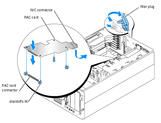
- Angle the RAC card so that its NIC connector inserts through the back-panel RAC card
opening, and then straighten the card. See Figure 6-20.
- Install the card:
- Hold the card by its edges with the holes in the corners of the card aligned with the four
plastic standoffs on the system board. See Figure 6-20.
- Carefully press the left end of the card onto the RAC card connector on the system board,
until the clips on the plastic standoffs snap over that end of the card. See Figure 6-20.
- Press down on the other end of the card until the remaining two standoffs fit over the
card edge.
- Reinstall the back fan bracket. See "Removing and Replacing the Back Fan Bracket."
- Reinstall the two memory module fans.
- Reinstall the memory cooling shroud.
- Close the system. See "Closing the System" in "Troubleshooting Your System."
- Reconnect the system and peripherals to their power sources, and turn them on.
- Enter the System Setup program and verify that the setting for the RAC card has changed to
reflect the presence of the card. See "Using the System Setup Program" in your User's Guide.
See the RAC card documentation for information on configuring and using the RAC card.
Back to Contents Page