Back to Contents Page
Installing System Options
Dell™ PowerEdge™ 2850 Systems Installation and Troubleshooting Guide
 System Fans
Power Supplies
Expansion-Card Cage
Expansion Cards
System Memory
Processors
System Battery
Installing an Optional RAC Card
This section describes how to remove and replace the following components:
- Expansion cards
- Memory upgrades
- Microprocessor upgrades
- RAC card
This section also includes instructions for replacing the fans, power supplies, and system battery, if necessary.
System Fans
The system includes the following hot-pluggable cooling fans:
- Two rear system fans
- Three front fans for one microprocessor or four front fans for two microprocessors
Removing a Cooling Fan

|
CAUTION: Only trained service technicians are authorized to remove the system cover and access any of the components inside the system. See your Product Information Guide for complete information about safety precautions, working inside the computer, and protecting against electrostatic discharge. |

|
NOTE: The procedure for removing each individual fan is the same. |

|
NOTICE: The cooling fans are hot-pluggable. To maintain proper cooling while the system is on, replace only one fan at a time. |
- Open the system. See "Opening the System" in "Troubleshooting Your System."
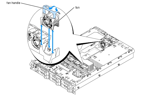
- Raise the fan handle and pull the fan straight up to clear the chassis. See Figure 6-1.
Figure 6-1. Removing and Installing a Cooling Fan
Replacing a Cooling Fan
|
|
NOTE: The procedure for installing each individual fan is the same. |
- Ensure that the fan handle is upright and lower the fan into its retention base until the fan is
fully seated. Then lower the fan handle until it snaps into place. See Figure 6-1.
- Close the system. See "Closing the System" in "Troubleshooting Your System."
Power Supplies
The system is available with optional two hot-pluggable power supplies.
Removing a Power Supply
|
|
NOTICE: The power supplies are hot-pluggable. The system requires one power supply to be installed for the system to operate normally. The system is in the redundant mode when two power supplies are installed. Remove and replace only one power supply at a time in a system that is powered on. |
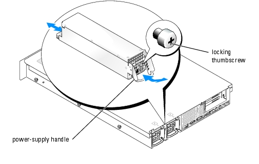
- Loosen the locking thumbscrew.
- Rotate the power-supply handle up until the power supply is released from the chassis. See
Figure 6-2.
- Pull the power supply straight out to clear the chassis. See Figure 6-2.
Figure 6-2. Removing and Installing a Power Supply
Replacing a Power Supply
- With the power-supply handle in the extended position, slide the new power supply into the
chassis. See Figure 6-2.
- Rotate the handle down until it is completely flush with the power-supply faceplate, and then
tighten the locking thumbscrew. See Figure 6-2.
|
|
NOTE: After installing a new power supply, allow several seconds for the system to recognize the power supply and determine whether it is working properly. The power-on indicator will turn green to signify that the power supply is functioning properly. See Figure 2-4. |
Expansion-Card Cage
The removable expansion-card cage simplifies many installation procedures by allowing you to remove the riser board and all installed expansion cards in a single step.
Removing the Expansion-Card Cage
|
|
CAUTION: Only trained service technicians are authorized to remove the system cover and access any of the components inside the system. See your Product Information Guide for complete information about safety precautions, working inside the computer, and protecting against electrostatic discharge. |
- Turn off the system, including any attached peripherals, and disconnect the system from the
electrical outlet.
- Open the system. See "Opening the System" in "Troubleshooting Your System."
- Disconnect all expansion-card cables.
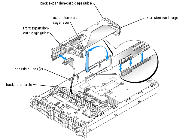
- Rotate the expansion-card cage lever up to a 90-degree angle until the cage is released from
the chassis. See Figure 6-3.
|
|
NOTE: The expansion-card cage lever pauses at a 45-degree angle, but is not unlocked. Continue rotating the lever to a 90-degree angle to unlock the cage. |
- Lift the cage straight up to clear the chassis. See Figure 6-3.
- Disconnect the backplane cable(s) from the riser board.
|
|
NOTICE: If two SCSI data cables are connected to the riser card, carefully note their relative locations so that you can reinstall them correctly. |
Figure 6-3. Removing and Installing the Expansion-Card Cage
Replacing the Expansion-Card Cage
|
|
CAUTION: Only trained service technicians are authorized to remove the system cover and access any of the components inside the system. See your Product Information Guide for complete information about safety precautions, working inside the computer, and protecting against electrostatic discharge. |
- Reconnect the backplane cable(s) to the riser board.
- With the expansion-card cage lever rotated to a 90-degree angle, align the guides on each end
of the expansion-card cage with the guides on the chassis wall, and lower the cage. See
Figure 6-3.
- Rotate the expansion-card cage lever down until the handle is flush with the top of the cage to
secure the cage in the chassis. See Figure 6-3.
- Reconnect all expansion-card cables.
- Close the system. See "Closing the System" in "Troubleshooting Your System."
Expansion Cards
The system is available with a PCI-X riser board or an optional PCI-X/PCI Express (PCIe) riser board. The PCI-X riser board provides three PCI-X expansion slots and the PCI-X/PCIe riser board provides one PCI-X expansion slot, one PCIe x4-lane expansion slot, and one PCIe x8-lane expansion slot
Expansion Card Installation Guidelines
PCI-X Riser Board Expansion Slots
Slot 1 and slot 2 share the same bus. Slot 3 is on a separate bus. You can install expansion cards of different operating speeds on the same bus; however, the bus will operate at the slowest operating speed of the cards on that bus. For example, if one card on the bus has an operating speed of 66 MHz and the other card has an operating speed of 100 MHz, the bus can operate only at 66 MHz. Also, if a PCI card is installed on the same bus with a PCI-X card, the bus runs in PCI mode.
|
|
NOTE: The expansion-card slots are not hot-pluggable. |
To identify expansion slots, see Figure A-4. Table 6-1 lists the operating speed for the PCI-X riser board expansion-card slots.
Table 6-1. PCI-X Riser Board Expansion Slot Speeds
|
Slot
|
Operating Speed
|
|---|
1
| 33, 66, 100, or 133 MHz
|
2
| 33, 66, 100, or 133 MHz
|
3
| 33, 66, 100, or 133 MHz
|
|
NOTE: Slot 3 supports half-length expansion cards only.
|
Optional PCI-X/PCIe Riser Board Expansion Slots
The optional PCI-X/PCIe riser board provides one PCIe x4-lane slot, one PCIe x8-lane slot, and one PCI-X 100-MHz slot.
|
|
NOTE: Although the PCIe x4-lane expansion slot is physically a PCIe x8 connector, it functions only as a PCIe x4-lane slot. |
|
|
NOTE: The expansion-card slots are not hot-pluggable. |
To identify expansion slots, see Figure A-5. Table 6-2 lists the PCI bus and operating speed for the optional PCI-X/PCI-e riser board expansion-card slots. The three expansion card slots are on separate buses.
Table 6-2. Optional PCI-X/PCIe Riser Board Expansion Slot Speeds
|
Slot
|
Operating Speed
|
|---|
1
| 2GB per second
|
2
| 4GB per second
|
3
| 33, 66, or 100 MHz
|
|
NOTE: Slot 3 supports half-length expansion cards only.
|
Installing an Expansion Card
|
|
CAUTION: Only trained service technicians are authorized to remove the system cover and access any of the components inside the system. See your Product Information Guide for complete information about safety precautions, working inside the computer, and protecting against electrostatic discharge. |
- Unpack the expansion card and prepare it for installation.
For instructions, see the documentation accompanying the card.
- Turn off the system, including any attached peripherals, and disconnect the system from the
electrical outlet.
- Open the system. See "Opening the System" in "Troubleshooting Your System."
- Disconnect all expansion-card cables.
- Remove the expansion-card cage. See "Removing the Expansion-Card Cage."
- Position the expansion-card cage so that the riser board lies horizontally or vertically on your
work surface.
|
|
NOTE: The horizontal or vertical orientation of the riser board depends on the type of card that you are installing. The horizontal orientation of the riser board shown in Figure 6-4 is for reference only. |
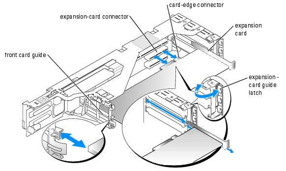
- Open the expansion-card guide latch and remove the filler bracket. See Figure 6-4.
- Install the expansion card:
- If the expansion card is full length, align its front edge with the front card guide. See
Figure 6-4.
- Position the expansion card so that the card-edge connector aligns with the expansion-
card connector on the expansion-card riser board.
- Insert the card-edge connector firmly into the expansion-card connector until the card is
fully seated.
- When the card is seated in the connector, close the expansion-card latch. See Figure 6-4.
Figure 6-4. Installing an Expansion Card
- Replace the expansion-card cage. See "Replacing the Expansion-Card Cage."
- Reconnect all expansion-card cables, including those for the new card.
See the documentation that came with the card for information about its cable connections.
|
|
NOTE: If the expansion card you are installing is of a different operating speed as the card already installed on the same PCI bus, all expansion cards on that bus will operate at the slower speed. |
- Close the system. See "Closing the System" in "Troubleshooting Your System."
Removing an Expansion Card
|
|
CAUTION: Only trained service technicians are authorized to remove the system cover and access any of the components inside the system. See your Product Information Guide for complete information about safety precautions, working inside the computer, and protecting against electrostatic discharge. |
- Turn off the system, including any attached peripherals, and disconnect the system from the
electrical outlet.
- Open the system. See "Opening the System" in "Troubleshooting Your System."
- Disconnect all expansion-card cables.
- Remove the expansion-card cage. See "Removing the Expansion-Card Cage."
- Position the expansion-card cage so that the riser board lies horizontally on your work surface.
- Release the expansion card:
- Open the expansion-card latch. See Figure 6-4.
- Grasp the expansion card by its top corners, and carefully remove it from the expansion-
card connector.
- If you are removing the card permanently, install a metal filler bracket over the empty
expansion slot opening and close the expansion-card latch.
|
|
NOTE: You must install a filler bracket over an empty expansion slot to maintain Federal Communications Commission (FCC) certification of the system. The brackets also keep dust and dirt out of the system and aid in proper cooling and airflow inside the system. |
- Replace the expansion-card cage. See "Replacing the Expansion-Card Cage."
- Reconnect all expansion-card cables.
- Close the system. See "Closing the System" in "Troubleshooting Your System."
System Memory
The six memory module sockets can accommodate from 256 MB to 16GB of registered ECC PC2-3200 (DDR 2 400) memory. The memory sockets are located on the system board under the memory module shroud adjacent to the power supply bays. See Figure A-3.
You can upgrade the system memory by installing combinations of 256-, 512-MB, 1-GB, 2-GB, and 4-GB (when available) registered memory modules. You can purchase memory upgrade kits from Dell.
|
|
NOTE: The memory modules must be PC2-3200 compliant. |
|
|
NOTICE: If you remove your original memory modules from the system during a memory upgrade, keep them separate from any new memory modules that you may have, even if you purchased the new memory modules from Dell. Use only registered ECC DDR II memory modules. |
The memory module sockets are arranged in three banks on two channels (A and B). The memory module banks are identified as follows:
- Bank 1: DIMM1_A and DIMM1_B
- Bank 2: DIMM2_A and DIMM2_B
- Bank 3: DIMM3_A and DIMM3_B
General Memory Module Installation Guidelines
- If only one memory module is installed, it must be a 256 MB module installed in socket DIMM_1A.
- If two or more memory modules are installed, they must be installed in pairs of matched memory size, speed, and technology.
- The system supports both single-ranked and dual-ranked memory modules.
Memory modules marked with a 1R are single ranked and modules marked with a 2R are dual ranked.
- If you install both single-ranked and dual -ranked memory modules, the dual-ranked memory modules must be installed in bank 1, regardless of capacity.
|
|
NOTE: Dual-rank memory modules with less capacity take precedence over single-ranked memory modules with greater capacity. |
- If bank 2 contains dual-ranked memory modules, then bank 3 must be unpopulated.
- Dual-ranked memory modules are not supported in bank 3.
Spare Bank Support
If six memory modules of the same size are installed, the memory modules in bank 3 (DIMM3_A and DIMM3_B) can function as a spare bank. The following restrictions apply when configuring memory for spare bank support:
- All six memory modules must be single-rank modules.
- All six memory modules must have the same capacity.
Memory Mirroring Support
The system supports memory mirroring if identical memory modules are installed in bank 1 and bank 2, and no memory modules are installed in bank 3.
Table 6-3 and Table 6-4 show examples of different memory configurations. Table 6-4 lists the various allowable combinations of single- and dual-ranked memory modules
Table 6-3. Sample Memory Configurations
|
Total Memory
|
DIMM_1A
|
DIMM_1B
|
DIMM_2A
|
DIMM_2B
|
DIMM_3A
|
DIMM_3B
|
|---|
256 MB
| 256 MB
| none
| none
| none
| none
| none
|
1 GB
| 256 MB
| 256 MB
| 256 MB
| 256 MB
| none
| none
|
1 GB
| 512 MB
| 512 MB
| none
| none
| none
| none
|
2 GB
| 512 MB
| 512 MB
| 512 MB
| 512 MB
| none
| none
|
2 GB
| 1 GB
| 1 GB
| none
| none
| none
| none
|
3 GB
| 1 GB
| 1 GB
| 512 MB
| 512 MB
| none
| none
|
3 GB
| 512 MB
| 512 MB
| 512 MB
| 512 MB
| 512 MB
| 512 MB
|
4 GB
| 1 GB
| 1 GB
| 1 GB
| 1 GB
| none
| none
|
4 GB
| 1 GB
| 1 GB
| 512 MB
| 512 MB
| 512 MB
| 512 MB
|
6 GB
| 2 GB
| 2 GB
| 1 GB
| 1 GB
| none
| none
|
6 GB
| 1 GB
| 1 GB
| 1 GB
| 1 GB
| 1 GB
| 1 GB
|
8 GB
| 2 GB
| 2 GB
| 2 GB
| 2 GB
| none
| none
|
8 GB
| 4 GB
| 4 GB
| none
| none
| none
| none
|
12 GB
| 2 GB
| 2 GB
| 2 GB
| 2 GB
| 2 GB
| 2 GB
|
16 GB
| 4 GB
| 4 GB
| 4 GB
| 4 GB
| none
| none
|
Table 6-4. Allowable Memory Module Configurations – Single-Ranked and Dual-Ranked Memory Modules
|
DIMM1_A
|
DIMM1_B
|
DIMM2_A
|
DIMM2_B
|
DIMM3_A
|
DIMM3_B
|
Single Rank
| none
| none
| none
| none
| none
|
Single Rank
| Single Rank
| none
| none
| none
| none
|
Dual Rank
| Dual Rank
| none
| none
| none
| none
|
Single Rank
| Single Rank
| Single Rank
| Single Rank
| none
| none
|
Dual Rank
| Dual Rank
| Dual Rank
| Dual Rank
| none
| none
|
Dual Rank
| Dual Rank
| Single Rank
| Single Rank
| none
| none
|
Single Rank
| Single Rank
| Single Rank
| Single Rank
| Single Rank
| Single Rank
|
Dual Rank
| Dual Rank
| Single Rank
| Single Rank
| Single Rank
| Single Rank
|
Installing Memory Modules
|
|
CAUTION: Only trained service technicians are authorized to remove the system cover and access any of the components inside the system. See your Product Information Guide for complete information about safety precautions, working inside the computer, and protecting against electrostatic discharge. |
- Open the system. See "Opening the System" in Troubleshooting Your System."
- Lift up the memory module shroud.
- Locate the memory module sockets. See Figure A-3.
- Press the ejectors on the memory module socket down and out, as shown in Figure 6-5, to
allow the memory module to be inserted into the socket.
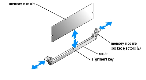
Figure 6-5. Installing and Removing a Memory Module
- Align the memory module's edge connector with the alignment key of the memory module
socket, and insert the memory module in the socket.
|
|
NOTE: The memory module socket has an alignment key that allows you to install the memory module in the socket in only one way. |
- Press down on the memory module with your thumbs while pulling up on the ejectors with
your index fingers to lock the memory module into the socket.
When the memory module is properly seated in the socket, the ejectors on the memory module socket align with the ejectors on the other sockets that have memory modules installed.
- Repeat step 3 through step 6 of this procedure to install the remaining memory modules. See
Table 6-3 and Table 6-4 for sample memory configurations.
- Lower the memory module shroud.
- Close the system. See "Closing the System" in "Troubleshooting Your System."
- Press <F2> to enter the System Setup program, and check the System Memory setting on
the main System Setup screen.
The system should have already changed the value to reflect the newly installed memory.
- If the value is incorrect, one or more of the memory modules may not be installed properly.
Repeat step 1 through step 10 of this procedure, checking to ensure that the memory modules
are firmly seated in their sockets.
- Run the system memory test in the system diagnostics. See "Running System Diagnostics."
Removing Memory Modules
|
|
CAUTION: Only trained service technicians are authorized to remove the system cover and access any of the components inside the system. See your Product Information Guide for complete information about safety precautions, working inside the computer, and protecting against electrostatic discharge. |
- Open the system. See "Opening the System" in Troubleshooting Your System."
- Lift up the memory module shroud.
- Locate the memory module sockets. See Figure A-3.
- Press down and out on the ejectors on each end of the socket until the memory module pops
out of the socket. See Figure 6-5.
- Lower the memory module shroud.
- Close the system. See "Closing the System" in "Troubleshooting Your System."
Processors
It is possible to upgrade your processor(s) to take advantage of future options in speed and functionality. Each processor and its associated internal cache memory are contained in a pin grid array (PGA) package that is installed in a ZIF socket on the system board.
The following items are included in the processor upgrade kit:
- Processor
- Heat sink
- Front fan
Replacing the Processor
|
|
CAUTION: Only trained service technicians are authorized to remove the system cover and access any of the components inside the system. See your Product Information Guide for complete information about safety precautions, working inside the computer, and protecting against electrostatic discharge. |
- Open the system. See "Opening the System" in Troubleshooting Your System."
- Lift up and remove the memory module shroud.
|
|
NOTICE: The processor and heat sink can become extremely hot. Be sure the processor has had sufficient time to cool before handling. |
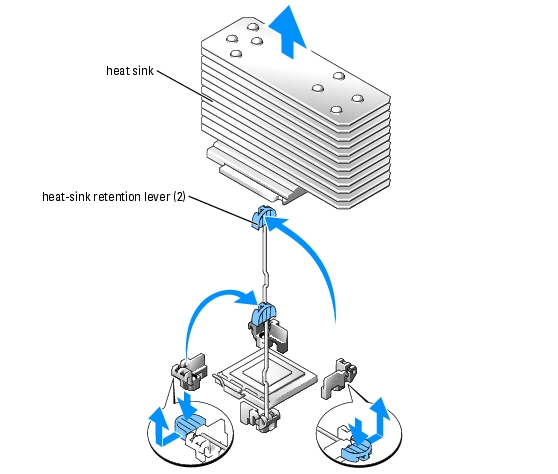
- Press the tab on the end of one of the heat-sink retention levers to disengage the lever, then
lift the lever 90 degrees. See Figure 6-6.
|
|
NOTICE: Never remove the heat sink from a processor unless you intend to remove the processor. The heat sink is necessary to maintain proper thermal conditions. |
Figure 6-6. Installing and Removing the Heat Sink
|
|
NOTE: When removing the heat sink, the possibility exists that the processor might adhere to the heat sink and be removed from the socket. It is recommended that you remove the heat sink while the processor is still warm. |
- Wait 30 seconds for the heat sink to loosen from the processor.
- Repeat step 3 to open the other heat sink retention lever.
- Remove the heat sink.
- If the processor is removed from the socket with the heat sink, twist or slide the processor
off of the heat sink. Do not pry the processor off of the heat sink.
- Set the heat sink upside down so as not to contaminate the thermal grease.
- Pull the socket-release lever straight up until the processor is released from the socket. See
Figure 6-7.
Figure 6-7. Installing and Removing the Processor
- Lift the processor out of the socket and leave the release lever up so that the socket is ready for
the new processor.
|
|
NOTICE: Be careful not to bend any of the pins when removing the processor. Bending the pins can permanently damage the processor. |
- Unpack the new processor.
If any of the pins on the processor appear bent, see "Getting Help."
- Align the pin-1 corner of the processor with the pin-1 corner of the ZIF socket. See
Figure 6-7.
|
|
NOTE: Identifying the pin-1 corners is critical to positioning the processor correctly. |
Identify the pin-1 corner of the processor by locating the tiny gold triangle on one corner of the processor. Place this corner in the same corner of the ZIF socket identified by a corresponding triangle.
- Install the processor in the socket.
|
|
NOTICE: Positioning the processor incorrectly can permanently damage the processor and the system when you turn it on. When placing the processor in the socket, be sure that all of the pins on the processor enter the corresponding holes. Be careful not to bend the pins. |
- If the release lever on the processor socket is not positioned all the way up, move it to that
position.
- With the pin-1 corners of the processor and socket aligned, set the processor lightly in the
socket, making sure all pins are matched with the correct holes in the socket.
Because the system uses a ZIF processor socket, do not use force, which could bend the pins if the processor is misaligned.
When the processor is positioned correctly, it drops down into the socket with minimal pressure.
- When the processor is fully seated in the socket, rotate the socket release lever back down
until it snaps into place, securing the processor.
- Install the heat sink.
- Using a clean lint-free cloth, remove the existing thermal grease from the heat sink.
|
|
NOTE: Use the heat sink that you removed in step 6. |
- Apply thermal grease evenly to the top of the processor.
- Place the heat sink onto the processor. See Figure 6-6.
- Close one of the two heat sink retention levers until it locks. See Figure 6-6.
- Repeat for the other heat sink retention lever.
- Install the new front fan in the empty fan connector in front of the new processor. See
"System Fans."
- Replace the memory module shroud.
- Close the system. See "Closing the System" in "Troubleshooting Your System."
As the system boots, it detects the presence of the new processor and automatically changes the system configuration information in the System Setup program.
- Press <F2> to enter the System Setup program, and check that the processor information
matches the new system configuration.
See your User's Guide for instructions about using the System Setup program.
- Run the system diagnostics to verify that the new processor operates correctly.
See "Running System Diagnostics" for information about running the diagnostics and troubleshooting processor problems.
System Battery
The system battery is a 3.0-volt (V), coin-cell battery.
Replacing the System Battery
|
|
CAUTION: Only trained service technicians are authorized to remove the system cover and access any of the components inside the system. See your Product Information Guide for complete information about safety precautions, working inside the computer, and protecting against electrostatic discharge. |
|
|
CAUTION: There is a danger of a new battery exploding if it is incorrectly installed. Replace the battery only with the same or equivalent type recommended by the manufacturer. Discard used batteries according to the manufacturer's instructions. See your System Information Guide for additional information. |
- Turn off the system, including any attached peripherals, and disconnect the system from the
electrical outlet.
- Open the system. See "Opening the System" in "Troubleshooting Your System."
- Lift up the memory airflow shroud.
- Locate the battery socket. See Figure A-3.
|
|
NOTICE: If you pry the battery out of its socket with a blunt object, be careful not to touch the system board with the object. Ensure that the object is inserted between the battery and the socket before you attempt to pry out the battery. Otherwise, you may damage the system board by prying off the socket or by breaking circuit traces on the system board. |
|
|
NOTICE: To avoid damage to the battery connector, you must firmly support the connector while installing or removing a battery. |
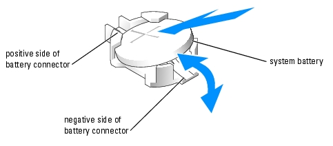
- Remove the system battery.
- Support the battery connector by pressing down firmly on the positive side of the
connector.
- While supporting the battery connector, press the battery toward the positive side of the
connector and pry it up out of the securing tabs at the negative side of the connector.
|
|
NOTICE: To avoid damage to the battery connector, you must firmly support the connector while installing or removing a battery. |
- Install the new system battery.
- Support the battery connector by pressing down firmly on the positive side of the
connector.
- Hold the battery with the "+" facing up, and slide it under the securing tabs at the
positive side of the connector.
- Press the battery straight down into the connector until it snaps into place.
- Lower the memory airflow shroud.
- Close the system. See "Closing the System" in "Troubleshooting Your System."
- Reconnect the system to its electrical outlet and turn the system on, including any attached
peripherals.
- Enter the System Setup program to confirm that the battery is operating properly. See "Using
the System Setup Program" in the User's Guide.
- Enter the correct time and date in the System Setup program's Time and Date fields.
- Exit the System Setup program.
- To test the newly installed battery, turn off the system and disconnect it from the electrical
outlet for at least an hour.
- After an hour, reconnect the system to its electrical outlet and turn it on.
- Enter the System Setup program and if the time and date are still incorrect, see "Getting
Help" for instructions on obtaining technical assistance.
Installing an Optional RAC Card
|
|
CAUTION: Only trained service technicians are authorized to remove the system cover and access any of the components inside the system. See your Product Information Guide for complete information about safety precautions, working inside the computer, and protecting against electrostatic discharge. |
- Turn off the system, including any attached peripherals, and disconnect the system from the
electrical outlet.
- Open the system. See "Opening the System" in "Troubleshooting Your System."
- Remove the two system fans. See "Removing a Cooling Fan."
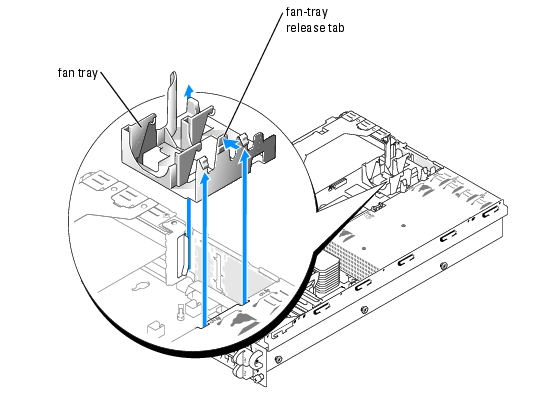
- Remove the fan tray:
- Press the fan-tray release tab. See Figure 6-8.
- Lift the fan tray straight up and out of the system.
Figure 6-8. Removing the Rear Fan Tray
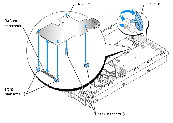
- Remove the plastic filler plug from the system back panel. See Figure 6-9.
- Angle the RAC card so that its NIC connector inserts through the back-panel RAC card
opening, and then straighten the card.
Figure 6-9. Installing a RAC Card
- Align the front edge of the RAC card with the two front plastic standoffs adjacent to the RAC
system board connector, and press down the front of the card until it is fully seated. See
Figure 6-9.
When the front of the card is fully seated, the two front plastic standoffs snap over the front edge of the card.
- Align the back edge of the RAC card with the two back plastic standoffs, and press down the
back of the card until it is fully seated. See Figure 6-9.
When the back of the card is fully seated, the two back plastic standoffs snap over the back edge of the card.
- Replace the back fan tray:
- Align the fan-tray alignment slot with the alignment tab on the side of the chassis wall.
See Figure 6-10.
- Align the alignment pin on the bottom of the fan tray with the alignment hole on the
system board.
- Slide the fan tray straight down.
- Press the two left latches until the release tab securely snaps into its securing slot.
Figure 6-10. Installing the Rear Fan Tray
- Replace the two rear system fans. See "Replacing a Cooling Fan."
- Close the system. See "Closing the System" in "Troubleshooting Your System."
- Reconnect the system and peripherals to their power sources, and turn them on.
- Enter the System Setup program and verify that the setting for the SCSI controller has
changed to reflect the presence of the RAID hardware. See "Using the System Setup Program"
in your User's Guide.
See the RAC card documentation for information on configuring and using the RAC card.
Back to Contents Page