 SCSI Interface Cables
Dell™ PowerEdge™ 2850 Systems Installation and Troubleshooting Guide
SCSI Configuration Information
Activating the Integrated RAID Controller
Installing a RAID Controller Card
Installing a SCSI Backplane Daughter Card
Your system contains up to six 1-inch SCSI hard drives. An optional optical drive and an optional diskette drive are mounted on separate trays that slide into the front panel and SCSI backplane board. This section contains instructions for replacing those drive devices.
SCSI interface connectors are keyed for correct insertion. Keying ensures that the pin-1 wire in the cable connects to pin 1 in the connectors on both ends. When you disconnect an interface cable, take care to grasp the cable connector, rather than the cable itself, to avoid stress on the cable.
Although SCSI devices are installed in essentially the same way as other devices, their configuration requirements are different. To configure an external SCSI device, follow the guidelines in the following subsections.
Each device attached to a SCSI host adapter must have a unique SCSI ID number from 0 to 15.
Set the tape SCSI ID using the jumper and switch settings on the drive to prevent conflict with any other device IDs on the bus. For default SCSI ID settings, refer to the tape drive documentation.

|
NOTE: There is no requirement that SCSI ID numbers be assigned sequentially or that devices be attached to the cable in order by ID number. |
SCSI logic requires that termination be enabled for the two devices at opposite ends of the SCSI chain and disabled for all devices in between. For internal SCSI devices, termination is configured automatically. For external SCSI devices, you should disable termination on all devices and use terminated cables. See the documentation provided with any optional SCSI device you purchase for information on disabling termination.
This subsection describes how to configure and install an external SCSI tape drive.

|
NOTICE: See "Protecting Against Electrostatic Discharge" in the safety instructions in your Product Information Guide. |
Ground yourself by touching an unpainted metal surface on the back of the system, unpack the drive (and controller card, if applicable), and compare the jumper and switch settings with those in the drive documentation.
See "SCSI Configuration Information," for information on setting the drive's SCSI ID number and enabling termination (if required). Change any settings necessary for your system's configuration.
|
|
NOTICE: See "Protecting Against Electrostatic Discharge" in the safety instructions in your Product Information Guide. |
Ground yourself by touching an unpainted metal surface on the back of the system, unpack the drive (and controller card, if applicable), and compare the jumper and switch settings with those in the drive documentation.
See "SCSI Configuration Information," for information on setting the drive's SCSI ID number and enabling termination (if required). Change any settings necessary for your system's configuration.
Hard drives bays are numbered 0 through 5 starting at the lower leftmost drive bay.
This subsection describes how to install and configure SCSI hard drives in the system's internal hard-drive bays.
Before attempting to remove or install a drive while the system is running, see the RAID documentation and ensure that the system is configured correctly to support hot-pluggable drive removal and insertion.
SCSI hard drives are supplied in special drive carriers that fit in the hard-drive bays.
|
|
NOTE: You should only use drives that have been tested and approved for use with the SCSI backplane board. |
You may need to use different programs than those provided with the operating system to partition and format SCSI hard drives. See "Installing and Configuring SCSI Drivers" in the User's Guide for information and instructions.
|
|
NOTICE: Do not turn off or reboot your system while the drive is being formatted. Doing so can cause a drive failure. |
When you format a high-capacity SCSI hard drive, allow enough time for the formatting to complete. Long format times for these drives are normal. For example, an exceptionally large drive can take over an hour to format.
The hard-drive bays provide space for up to six 1-inch SCSI hard drives. The hard drives connect to a controller on the system board or a RAID controller card through the SCSI backplane board.
The system provides several options for hard drive configurations:
See "Installing a SCSI Backplane Daughter Card."
See Figure A-6 to locate the connectors on the SCSI backplane board.
|
|
NOTICE: When installing a hard drive, ensure that the adjacent drives are fully installed. Inserting a hard-drive carrier and attempting to lock its handle next to a partially installed carrier can damage the partially installed carrier's shield spring and make it unusable. |
|
|
NOTICE: Not all operating systems support hot-plug drive installation. See the documentation supplied with your operating system. |
Figure 7-1. Installing a SCSI Hard-Drive
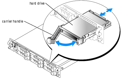
|
|
NOTICE: Do not insert a hard-drive carrier and attempt to lock its handle next to a partially installed carrier. Doing so can damage the partially installed carrier's shield spring and make it unusable. Ensure that the adjacent drive carrier is fully installed. |
|
|
NOTICE: Not all operating systems support hot-plug drive installation. See the documentation supplied with your operating system. |
If the drive has been online, the drive status indicator will blink green two times a second as the drive is powered down. When all indicators are off, the drive is ready for removal.
See your operating system documentation for more information on taking the hard drive offline.
If you are permanently removing the hard drive, install a blank insert.
An optional optical drive and an optional diskette drive are mounted on trays that slide in the front panel and connect to the controllers on the system board through the SCSI backplane board.

|
CAUTION: Only trained service technicians are authorized to remove the system cover and access any of the components inside the system. See your Product Information Guide for complete information about safety precautions, working inside the computer, and protecting against electrostatic discharge. |
Figure 7-2. Removing and Installing the Optical Drive or Diskette Drive Tray
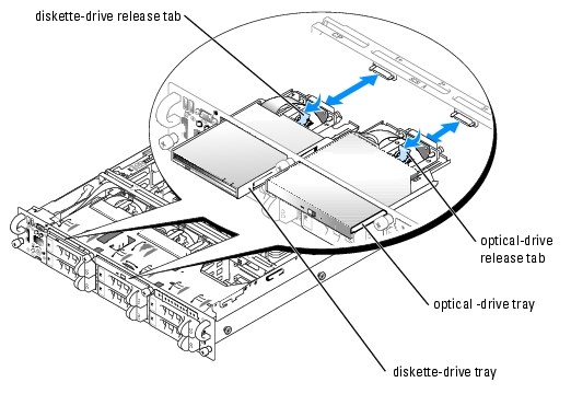
The optical drive opening is above hard-drive slots 2 and 3 and the diskette drive opening is above hard-drive slots 0 and 1 (the hard-drives slots are identified by labels on the front panel of the system).
|
|
CAUTION: Replace the battery only with the same or equivalent type recommended by the manufacturer. Discard used batteries according to the manufacturer's instructions. See the Product Information Guide for additional information. |
|
|
CAUTION: Only trained service technicians are authorized to remove the system cover and access any of the components inside the system. See your Product Information Guide for complete information about safety precautions, working inside the computer, and protecting against electrostatic discharge. |
|
|
NOTICE: To avoid possible data loss, back up all data on the hard drives before changing the mode of operation of the integrated SCSI controller from SCSI to RAID. |
See Figure A-4 or Figure A-5 to locate the RAID memory module connector on the expansion-card riser board.
The memory module connector has an alignment key that allows the memory module to be installed in the connector in only one way.
|
|
NOTE: The RAID controller memory module must be a 256MB, registered DDR2 (PC3200) memory module, rated to run at 400 MHz or faster. |
Figure 7-3. Installing the RAID Controller Memory Module
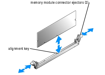
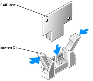
Figure 7-4. Installing the RAID Hardware Key
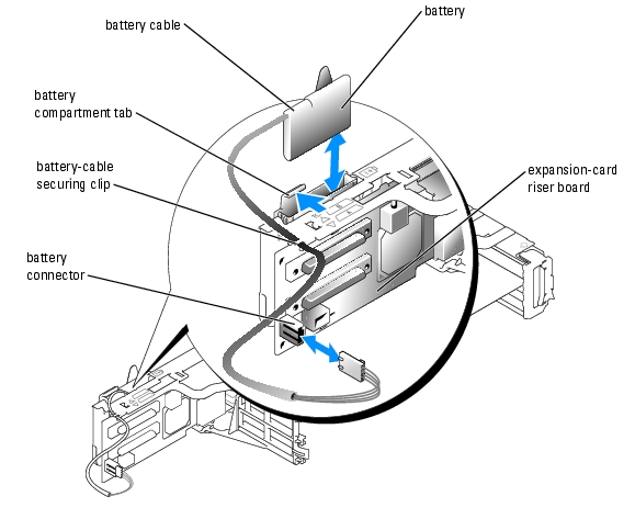
See Figure A-4 or Figure A-5 to locate the RAID battery cable connector on the expansion-card riser board.
Figure 7-5. Removing and Installing the RAID Battery
See the RAID documentation for more information.
|
|
CAUTION: Only trained service technicians are authorized to remove the system cover and access any of the components inside the system. See your Product Information Guide for complete information about safety precautions, working inside the computer, and protecting against electrostatic discharge. |
Follow these general guidelines when installing a RAID controller card. For specific instructions, see the documentation supplied with the RAID controller card.
For instructions, see the documentation accompanying the card.
|
|
NOTE: Cables can be connected from the RAID controller card to SCSIA and/or SCSIB backplane board connector(s). A backplane board connector that is not attached to the RAID controller card uses the integrated SCSI controller or optional integrated RAID controller if it is attached to the riser board. |
To identify the connector on the RAID controller card, see documentation for the card. See Figure A-6 to locate the SCSI controller connectors on the SCSI backplane board.
Route the SCSI cables over the SCSI backplane board to the expansion-card cage.
If you are attaching multiple external SCSI devices, daisy-chain the devices to each other using the cables shipped with each device.
Test a SCSI hard drive by running the SCSI Controllers test in the system diagnostics.
|
|
CAUTION: Only trained service technicians are authorized to remove the system cover and access any of the components inside the system. See your Product Information Guide for complete information about safety precautions, working inside the computer, and protecting against electrostatic discharge. |
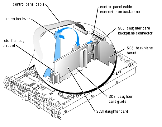
To operate the SCSI backplane in a 2/4 split backplane configuration, you must install a daughter card.
The SCSI backplane daughter card connector and card guide are located in the compartment below the control panel cable.
Figure 7-6. Installing a SCSI Backplane Daughter Card
See Figure A-6 to locate the connectors on the SCSI backplane board.
If you plan to boot the system from a hard drive, the drive must be attached to the primary (or boot) controller. The device that the system boots from is determined by the boot order specified in the System Setup program.
The System Setup program provides options that the system uses to scan for installed boot devices. See your system's User's Guide for information about the System Setup program.